Sensors for Robots
Sensors play a significant role in any robot, whether it is autonomous, semi-autonomous or remotely-controlled by a human. These sensors help a robot communicate with its external world, or control its own internal system. Before we understand the different sensors, we will understand what “senses” are and what they do.
 A sense with regards to living organisms is the capability to perceive its environment. The five Aristotelian senses of human being are Sight, Hearing, Touch, Smell and Taste. More and more research in this field led to a belief that there are more than five senses. Few argue that there are almost 21 sensors in a human body which includes thermoception (sensing temperature variation), equilibrioception (sense to maintain balance), nociception (pain sensors), kinesthesioception(sensing acceleration) etc., These senses help us sense our environment and act accordingly.
Since it is difficult to implement these biological sensors, robots use electromechanical sensors that measure a physical quantity and convert it into signals that can be read, monitored and analyzed for further action.
The following section will help you identify the different sensors available for robots and also understand how they work.
Analog Sensors vs. Digital Sensors
The output generated from sensors can be either analog signals or digital signals.
Analog Sensors
Analog Sensors output a change in electrical property to signify a change in its environment. The change can be a variation in Voltage, Current, Resistance, Charge and Capacitance. Sensor circuits are designed to monitor these changes and provide a voltage difference.
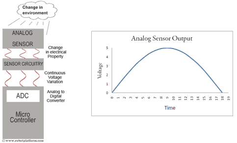
This voltage difference, if required can be converted into a digital value and processed further. All modern microcontrollers have Analog to Digital converter circuitry built-in. For example, if we consider a Photoresistor, the resistance in a Photoresistor changes with the amount of light falling on it. The Photoresistor circuitry creates a voltage difference based on the change in resistance and an analog signal is fed into the microcontroller. This analog signal, if required can be further converted into a digital value and processed as per the requirement (For further information, suggest you to read Analog to digital Conversion). Since most microcontrollers work within the 0V to +5V range, the sensor circuitry is designed such that it generates a continuous signal between 0 Volts to +5 Volts as an output.
Digital Sensors
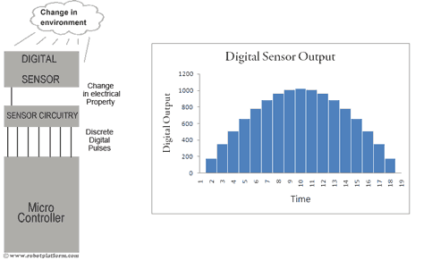
Unlike Analog sensors, digital sensors produce discrete digital pulses for a change in its environment. A push button switch is a very good example of a digital sensor. The output of this sensor can be either “ON” or “OFF”, i.e. it can be either 1 or 0.
There are other digital sensors which output a series of digital pulses, or binary values. For example, a sensor can output a 10 bit binary value 0000000000 to 1111111111 (decimal equivalent of 0 to 1023) to signify a change. This means a sensor can produce one of 1024 values to suggest a change in its environment.
It is important to realize this distinction between analog and digital outputs before selecting a sensor for your robot. Digital signals may seem easy to obtain and process, but involves a lot of calculations. The timer control in a microcontroller in itself is a nightmare. On the other hand, analog signals can be directly fed into a microcontroller, converted into a digital value using its built-in ADC and the information can be used as required.
Do you have anything to say?
Visit the Forum to discuss, learn and share anything related to robotics and electronics !!


