ADC Tutorial : Analog to Digital Conversion
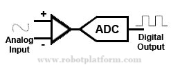 In simple words, Analog to Digital converter is an electronic device which converts analog signal from our real world into a machine readable or binary or digital format. For this all you need is a component which can convert physical real world analog signals into voltage signals. This voltage is fed into an ADC resulting in binary digits that can be processed further as per requirements.
Theoretically the concept is simple, but the circuit within, implementation and programming is more complex in reality which makesADC almost a nightmare to beginners. In this tutorial, we will learn the background of ADC first and then dig into actual programming. Though it might turn out to be a lengthy tutorial, suggest you to read and understand the whole tutorial to get a solid grip on ADC. Be informed that this is one of the most important topics in microcontroller programming. But I still give you a choice; If you too lazy to read the entire tutorial or if you are already aware of all these concepts, then skip the basics and directly jump into programming ADC.
Analog & Digital Signals
First let us break these three terms: Signals, Analog Signals & Digital Signals. Signals are set of values that convey information and are measured by any independent attribute like time or space. As an example sound is a signal and speed of sound is measured against time and distance which are independent attributes.
At an ADC point of view, we can differentiate signals as either analog or digital. Analog signals are continuous signals which vary with time. Digital signals have discrete meaningful steps varying over time. As an analogy, consider a fan regulator and an electric switch. Fan regulator can be adjusted to increase or decrease the speed of fan in a continuous manner whereas an electric switch can be either turned on or turned off,which is discrete.
 Although most of real world signals are analogous in nature viz. light, heat, sound etc., digital signals are equally important as microcontrollers and other digital systems are digital in nature. This is exactly where our ADC fits in. It helps us in converting the analogous signal into digital format.
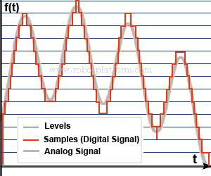
Analog to digital conversion is taking sample data of an analog signal and quantify it in a meaningful way. In other words, consider a wave (analog signal) as shown in the figure to the right. Suppose we add breakpoints to thiswave and determine the value at each breakpoint, then we are taking a snapshot of the wave at particular points with respect to time.
This process is known as “Sampling” and the number of samples processed by any device in a certain amount of time is measured in Samples per second (Sa/s), or KSa/S which is Kilo samples per second, or generally written as KSPS. Whenever we need to use ADC in any circuit, we need to check the conversion rate of that particular ADC.
Since there is possibly infinite range of values in an analog signal, it is significant to sample a finite set of discrete values out of that signal, and preferably with minimum loss. This process of converting continuous range of values into finite set of discrete values is called “Quantization” and each of these values are commonly known as “Quantization levels”.Since we take only a finite set of values, there will always be a difference between actual analog value and the quantized digital value. This difference is known as “Quantization Error”, or “Quantization Distortion”.
Each of these sample signals in the finite set is electronically stored in binary form, i.e. in bits. The number of bits used to represent a signal is called “resolution”. If we check the datasheet and it says “10 bit resolution”, then it means 10 bits are used to represent each signal in the sample, which is 2^10 = 1024 bits for each signal. Consequentlythere will be 2^n levels for an ADC with “n” bit resolution. Generally more number of bits gives out a better digitized picture of the original analog signal.
Electrically this resolution is expressed in volts. Voltage resolution of ADC is equal to overall voltage measurement range divided by number of discrete values or ADC’s bit resolution.
Consider the following example to better understand voltage resolution:
Maximum Voltage: VHigh = 5 Volts
Minimum Voltage: VLow = 0 Volts
Full measurement voltage (EFSR) = VHigh - VLow= 5V– 0 V = 5V
ADC resolution (N) = 10 bits= 2^10 = 1024 levels
Therefore, ADC voltage resolution (Q) = EFSR/ N = 5 / 1024 = 0.00488 V or 4.88 mV.
Now we can say that the resolution of 10 bit ADC over a range of 5 volts is 4.88 mV. When we refer to Atmega8 datasheet, it says that absolute accuracy in AD conversion can be ± 2 LSB, meaning the accuracy after conversion can be over or under 2 levels. Since ADC voltage resolution derived above is 4.88 mV, it can be considered that the absolute accuracy after conversion can be 4.88 * 2 = +/-9.77mV of the derived value.
Tutorial index:
Do you have anything to say?
Visit the Forum to discuss, learn and share anything related to robotics and electronics !!


