ADC implementation
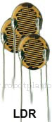 If you are clear with above concept, let us see how we can implement ADC. First and foremost, we need a component which can convert energy in our analog world into electrical signals. For this we use what is generally known as a “transducer”. A transducer is a sensor/device which converts energy from one form to another. It can be to/from electrical, photovoltaic, sound, electromagnetic to any other form of energy. Suppose we need to convert light energy into electrical energy, we use a Photo resistor or a Light Dependant Resistor (LDR). The resistance of this sensor changes with change in light intensity. Other examples of transducer are Accelerometer, Laser light, tactile sensor, thermistor etc. In the following tutorial, we will use a variable resistor as a transducer. The output voltage from these transducers are fed into the ADC and processed further. However, do note that the voltage sent from these transducers should be within acceptable level of the ADC. If the ADC voltage range is 0 to 5V, then the transducer circuit must output voltage only within this range. If not? As usual, we get unexpected results which might also include turning the entire circuit into white fumes.
Once the signals are sent to ADC, it processes those signals using internal circuitry and gives out a digital output. To do this, manufactures employ different ADC architecture within the circuitry to convert these signals. There are several architectures available for different tasks, based on the sampling rate, accuracy and design. Some of the known architectures are: Direct conversion ADC, Integration based ADC, Pipeline ADC, Flash ADC, Counter based conversion, etc. Atmel uses “Successive-approximation ADC” architecture. Let us discuss this method in detail.
Successive-approximation ADC (SAR ADC)
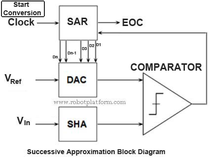
SAR ADC is one kind of ADC architecture which works on binary search method. Although it is much slower than other models like Pipeline and Flash ADC, power consumption is very low and a model of choice for low power devices. The working principle of SAR ADC seems reasonably complex, but not actually. The following sub-circuits make up the SAR ADC:
- Sample and Hold Circuitry (SHA)
- Digital-to-Analog converter circuit (DAC)
- Analog voltage comparator (COMPARATOR)
- Successive approximation register circuit (SAR)
Other aspects of SAR ADC are:
- VIn: Input Voltage
- VRef: Reference Voltage
- EOC: End of conversion
SHA circuit is used to acquire and hold input voltage (VIn) from transducer circuit to ensure that the voltage remains constant during conversion. DAC supplies an analog input voltage (VRef) to Comparator. Comparator compares the input from DAC and SHA and the result is stored in SAR. SAR provides DAC with appropriate digital code so that DAC outputs necessary analog voltage to Comparator. SAR also holds the result from comparator in its register. Once all the comparison is completed, the resulting digital equivalent of the analog signal is output and is end of the conversion (EOC).
Working principle
When the controller initiates and sends an ADC START signal to ADC unit, SHA acquires and holds the sample analog voltage from transducer circuit. SAR is cleared and MSB (most significant bit) in SAR is set to digital 1. This digital code is fed into DAC which is set to midscale and outputs an analog equivalent of the digital code. To explain midscale further, suppose the reference voltage is VRef, then midscale voltage of VRef is (VRef/2). Output from DAC and output from SHA is fed into comparator; comparator compares the reference voltage (from DAC) and sample voltage (from SHA). If reference voltage (VRef) is greater than sample voltage (Vin), then MSB is cleared (set to 0) else retained as 1.
Then the next bit is set to 1 and similar binary search is done until all the bits in SAR are tested till LSB (least significant bit). The resulting code in SAR is the digital output of the analog input.
Confusing? I guess it is. Let us take an example. Suppose the input voltage is 3.6 Volts (X) and is checked over a 10 bit ADC. Controller voltage is 0V (Vmin) to 5V (Vmax). DAC is set to midscale which means, reference voltage = 5/2 = 2.5 Volts. Now the procedure follows as given below; the comparator checks if X >= reference voltage; If yes, then retain else discard and move on to next bit
| Condition | Value | Bit Status | Result |
Is X >= 2.5 |
Yes | 1 | Retain -> 2.5 |
Is X >= 2.5+2.5/2 = 3.75 |
No | 0 | Discard -> 1.25 |
Is X >= 2.5+0.625 = 3.125 |
Yes | 1 | Retain -> 0.625 |
Is X>= 3.125 + 0.3125 = 3.4375 |
Yes | 1 | Retain -> 0.3125 |
Is X>= 3.4375 + 0.15625 = 3.59375 |
Yes | 1 | Retain -> 0.15625 |
Is X>= 3.59375 + 0.078125 = 3.671875 |
No | 0 | Discard -> 0.078125 |
Is X>= 3.59375 + 0.0390625 = 3.6328125 |
No | 0 | Discard -> 0.0390625 |
Is X>= 3.59375 + 0.01953125 = 3.61328125 |
No | 0 | Discard -> 0.01953125 |
Is X>= 3.59375 + 0.009765625 = 3.603515625 |
No | 0 | Discard -> 0.009765625 |
Is X>= 3.59375 + 0.0048828125 = 3.5986328125 |
Yes | 1 | Retain -> 3.5986328125 |
The digital equivalent of analog input from SAR is 1011100001(2). Suppose we require an 8 bit resolution, then the digital equivalent is 10111000(2).In AVR devices, by default result is stored in two registers namely ADCH and ADCL, where the first two bits are stored in ADCH and remaining 8 bits are stored in ADCL. In the later part of the tutorial we will see how we can find the voltage equivalent of this digital value.
Tutorial index:
Do you have anything to say?
Visit the Forum to discuss, learn and share anything related to robotics and electronics !!


