Photoresistors / LDR’s / CDS cells / Photoconductor
The name itself tells us what the component does. 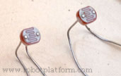 "Photo" is for light and "resistor" is to resist the flow of current. Let us dig in detail and understand what it does and how it does it.
Photoresistors, also known as Light Dependent Resistor (LDR), Cadmium Sulfide cells (CDS cells), Photoconductor and sometimes simply Photocells are a type of transducer which converts energy from one form to another where one of the known forms is electrical energy. To keep things simple, we will refer to it as Photoresistor. Resistance in a Photoresistor inversely varies with the amount of light it is exposed to. Bright light = Less resistance and Low light = more resistance. These sensors are used to make light sensitive devices and are more often found in street lights, cheap toys, outdoor clocks etc., if you have ever wondered how a street light turns on in the night and switches off in the day, you will be surprised to find a cheap photoresistor circuitry inside it.
Note: Phototransistors/Photodiodes/Photovoltic cells are altogether different and do not confuse that with these photoresistors.
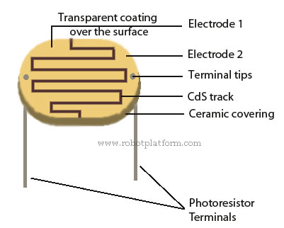
Cadmium Sulfide is often used to make these components due to its low cost. Other materials such as Lead sulfide, Indium antimonide and Lead Selenideare also used for high end requirements.
But how do they work?
Working principle of a photoresistor is relatively simple. If you have already read electricity basics, you know that electricity is nothing but movement of electrons within a material. Conductors have low resistance and insulators have high resistance. The third category is the semiconductors which stand between a conductor and an insulator. Photoresistor is made of one such semiconductor with very high resistance with only a few free electrons. When light falls on this material, photons from light is absorbed by these materials and energy is transferred to electrons which break up resulting in lower resistance and higher conductivity. The resistance in low light to bright light can be thousands of ohms. When exposed to low light, the resistance in a Photoresistor can be several mega-ohms (5-20 MΩ dependent on the type & size) and in bright light it results in only a few hundred ohms. Also photoresistors are non-polarized, meaning it can be connected either way in a circuit.
You can easily connect the leads with a multimeter on resistance mode and check resistance of your photoresistor. Face it towards bright light and check the resistance. Now place your hand or cover it up with a black tape and check the resistance again. You see that the resistance drastically increases once you cover the photoresistor.
For our robot circuitry we tend to use Cadmium Sulfide cells which come with their own advantages and disadvantages. Knowing the demerits beforehand helps in deciding whether we need to use it or consider any other available options.
Advantages:
- Cheap and will not make a hole in your pocket if you spoil few
- Commonly found in most robot hobby shops
- Available in different sizes with different specifications
- Easy to design and implement them in a circuitry
Drawbacks:
- Highly inaccurate. Each one behaves differently than the other. If the first one has a resistance of 150Ω in bright light, second one can have 500Ω of resistance in the same light
- They cannot be used to determine precise light levels
- Very slow for sensitive applications. If you put a LDR in a speeding robot and tell it to stop at an obstacle, you end up seeing your robot crash.
Although there are other drawbacks, it is always a given choice for beginners due to its simplicity.
Photoresistors although increase voltage with increase in light, an intelligent circuit can make it work otherwise with a combination of resistors. As an example if you design a LED which dims with more light and brightens up in the night, you would require this circuit. In the next section we will see how to connect them with a resistor to directly connect with a microcontroller.
Do you have anything to say?
Visit the Forum to discuss, learn and share anything related to robotics and electronics !!


