AVR Development board, Step-by-Step-Tutorial
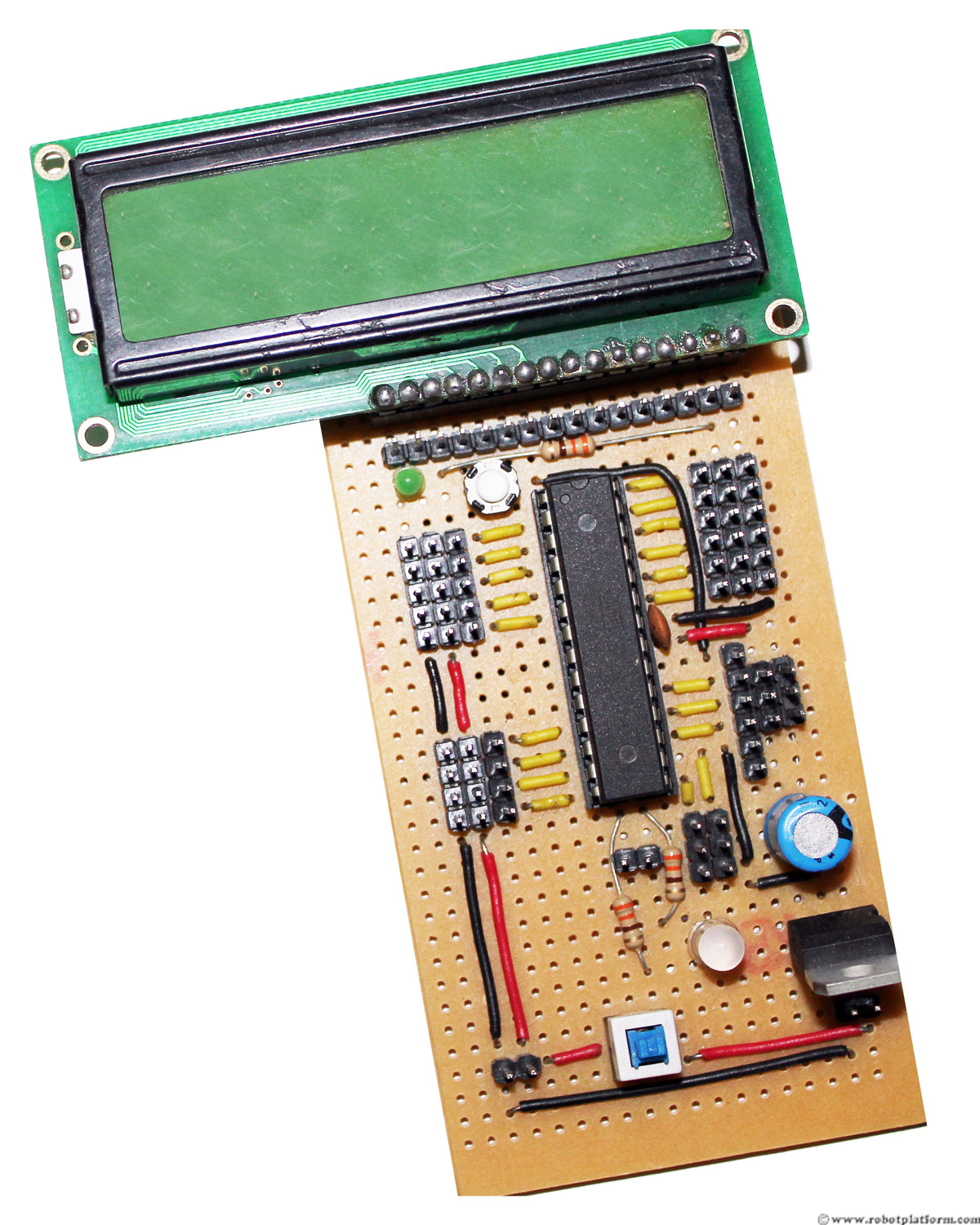
How to build an Atmega8 development board
If you ever wanted to build a robot but do not know where to start, then this tutorial is for you. For building a robot, you need a circuit board which can transfer your thoughts to the robot controllers. Once you have this board in hand, you can utilize the resources in this site or across the web to build your own robot. The board developed here acts as a platform for further robot development. Although there are many tutorials which shows DIY development boards, most of them lack a step-by-step tutorial with relevant pictures for a beginner to understand. They also include complicated schematics which are difficult for a beginner to understand. I intend to make this tutorial so detailed with relevant pictures that you might find it difficult to find an equivalent one ;)
Basics
In this tutorial, I would take you by hand (literally) and help you build a development board based on an atmega8 microcontroller (don’t worry if you don’t understand this yet). Since this is the first step in making robots, I would give a little background on this development board and continue with the tutorial.
First of all, what is a robot and why do you need to build one? Unless you have come to this site by mistake, I would presume that you know what a robot is, and would like to build a robot. If you are awestruck seeing a robot in a robot club or a competition, then take up this challenge today and start making robots.
Introduction
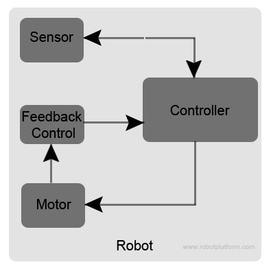
Robot is an electromechanical controlled device. If this is confusing, read it like this “A robot is a combination of electronics, mechanics and programming. User instructs a robot to perform an activity through a program which is fed into the controller, and the controller controls the electronics and mechanics to perform an activity”.
Let us take an example. Suppose you want to build a robot with four wheels, driven by four individual motors which is driving forward. A sensor (which is an electronic device that senses its environment and provides feedback) senses an obstacle in front of the robot and notifies a controller. The controller in turn changes the direction of rotation of motors making the robot turn sideways or reverse, thus avoiding an obstacle. This is a simple example of a robot; the controller which controls this robot is what we aim to design and build.
I guess, by now you should have a vague idea of what a controller is. The controller is an Atmega8 microcontroller which acts as your robot's brain. If you have not understood few terminologies, keep going. Read till the end of this tutorial and you will be mentally prepared to build a robot. Click on any image for an enlarged high resolution view; If the step in the tutorial requires soldering, then the particular section of the board is highlighted.
Why not purchase a readymade board?
You can!! There are many places where you can purchase a readymade board in which all you do is plug and play. However there are many reasons why you should consider building your own board. Some of the reasons are:
- Gives you hands on experience and the thrill of making your own board
- It sometimes makes sense to design a robot from ground up
- Costs almost a fraction of what ready boards cost
- Expect to gain a lot of experience in designing and soldering
DIY boards do come with few limitations
- The boards you build may not look as beautiful as those over the shelf
- Code snippets are readily available in the market for those tried and tested boards
- Good for a weekend project when time is a restriction and you do not like taking risks
- DIY boards are less reliable than readily available boards (although my experience suggests the othe way:)
If the advantages of building your own board has impressed you, then get ready to make your hands dirty.
Below is a list of parts required:
Note: I have not mentioned the price of any components or parts as they are different in different locations. Drop a line in the forum if you need the price of components at your specific location and I will try my best to get you the details. But I am sure you have more information about your location than me.
Parts required
| Parts | Details | Quantity |
Atmega8 Microcontroller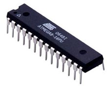 Atmega8 Microcontroller |
Microcontroller from Atmel | 1 |
Perforated board 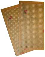 Perforated board |
With 36x20 or more holes | 1 |
Male breakaway headers 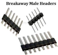 Male Breakaway Headers |
40 pin single row headers | 3 to 4 pcs |
Connecting wires 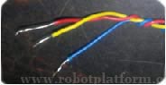 Wire |
Any 3 colors | 1 meter each |
LED 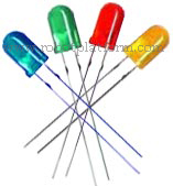 LED |
3mm green LED | 1 |
Solder 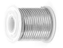 Solder Lead |
Lead / Lead free | 50-100 gms |
Solder Iron 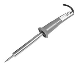 Solder Iron |
Preferably temperature controlled | 1 |
Resistor 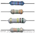 Resistor |
330Ω | 1 |
7805 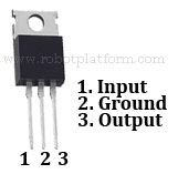 7805 |
Linear Voltage Regulator | 1 |
Ceramic Capacitor 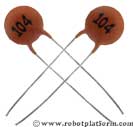 Ceramic Capacitor |
Code = 104, Value = 0.1 µf | 1 |
Electrolytic Capacitor 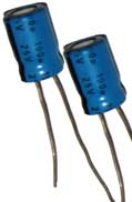 Electrolytic Capacitor |
25V, 100 µF | 1 |
28 Pin Socket 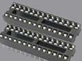 28 Pin Socket |
DIP socket for microcontroller | 1 |
Reset Button Switch 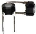 Reset Button Switch |
(Reset switch) with two leads | 1 |
Push Button Switch 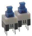 6 Pin Switch |
6 leads | 1 |
Optional list
| Parts | Details | Quantity |
Solder Wick 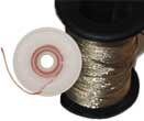 Solder Wick |
18 – 42 AWG | 1 reel |
Flux 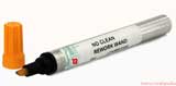 Flux Pen |
Rosin flux | Pen/Tin/Box |
Female Breakaway Header 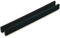 Female Breakaway Header |
40 pin single row headers | 1 |
Multimeter  Multimeter |
Digital Multimeter | 1 |
Computer 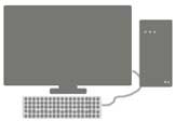 Computer |
With serial port | 1 |
Programmer 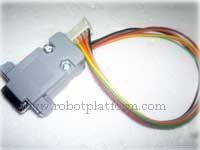 Serial Programmer |
For programming microcontroller | 1 |
* µf = Micro Farad, O = Ohm, DIP = Dual in-line package, V=Volts, mAh = milliampere-hour, pc = pieces, gms = grams, AWG = American wire gauge
Little fundamentals of components used, and additional tools required…
Atmega8 Microcontroller (µc): Microcontroller is an integrated circuit with physical pins coming out of it and acts as a brain to your robot. Pins in a microcontroller can be used to accept input and provide output, and further be connected to additional peripherals. In this tutorial we will use Atmega8 AVR microcontroller manufactured by Atmel (use Atmega8a, Atmega8/L if you cannot find Atmega8). For those of you who require technical information, Atmega8 is a feature rich pack which includes 8KB of programmable memory, 1KB of RAM, 512 bytes of EEPROM, 23 I/O pins, and lot more additional features for a beginner to experiment with.
Perforated board (Perfboard) is a thin rigid sheet with holes in it, used for prototyping electronic circuits. The holes have a square or a round copper layer around it (known as copper pad or solder pad) which helps while soldering electronic components to it. I have used a board with holes 36x20 and you are free to use a bigger board if you have one. If you use a smaller one, then you may not be able to enjoy the benefits of adding additional headers for LCD, but go ahead if you want to…
28 Pin socket a holder for your microcontroller. Obviously you can solder the microcontroller pins directly to the board. But having a socket makes life easier so that you can plug-in and pull-out your microcontroller when required.
Multimeter: It is extremely difficult to find a cross connection, short or a break in a circuit without a Multimeter. Use it if you have one, or can borrow it from a friend. If not, hope that you do not make any mistakes and continue with the tutorial.
Computer/Laptop: If you want to test your development board, you need a computer or a laptop to program your microcontroller.
Programmer: A programmer helps you to transfer your files from your computer to the microcontroller. Programmer interface can be serial, parallel or USB. If you purchase a serial/parallel programmer, make sure your laptop has a serial/parallel interface.
Tutorial index:
Do you have anything to say?
Visit the Forum to discuss, learn and share anything related to robotics and electronics !!


