AVR Development board, Step-by-Step-Tutorial
How to build an Atmega8 development board
Adding Programmer Pins
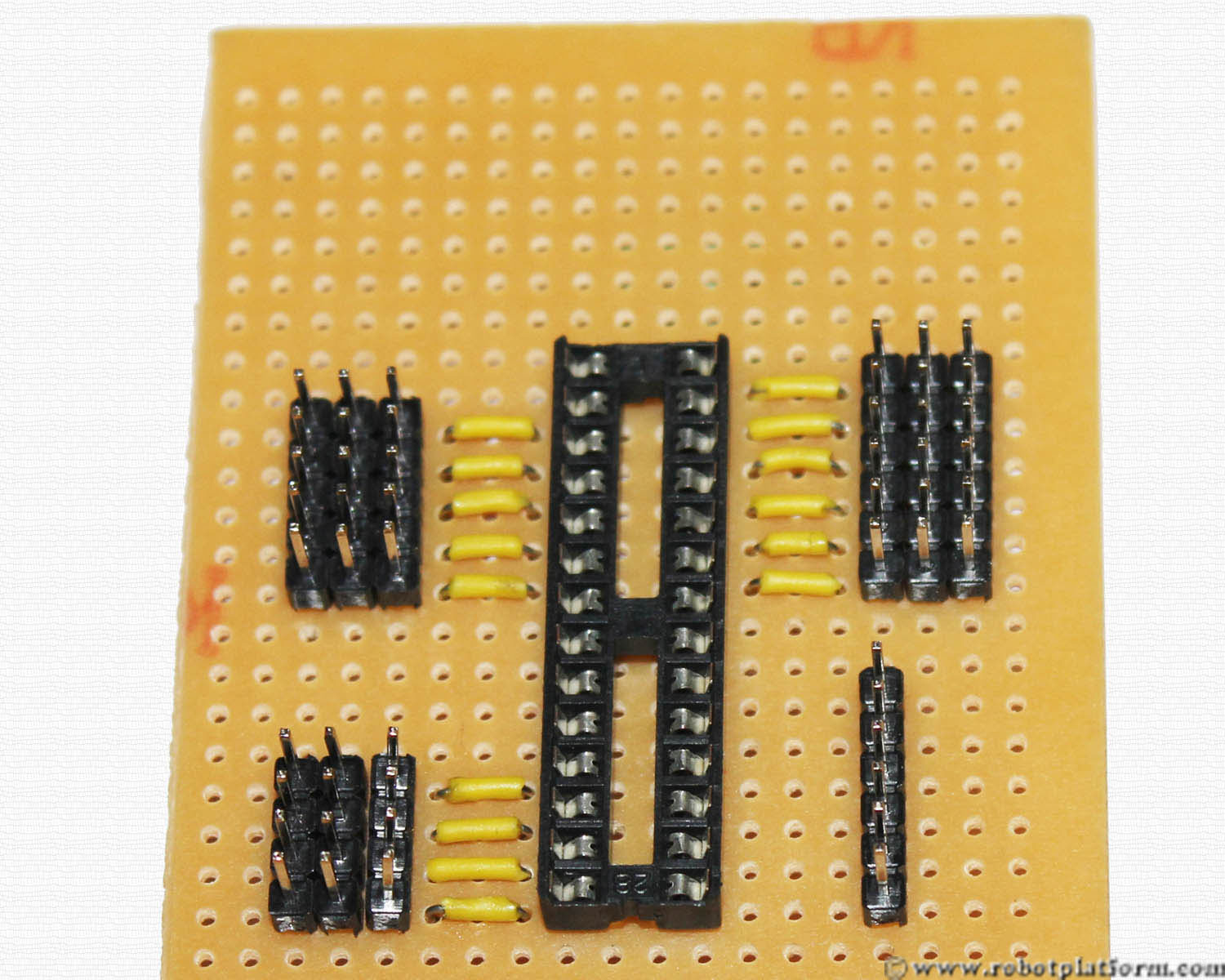
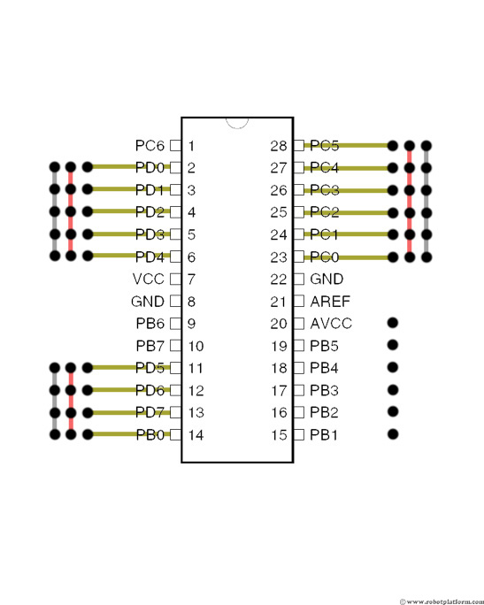
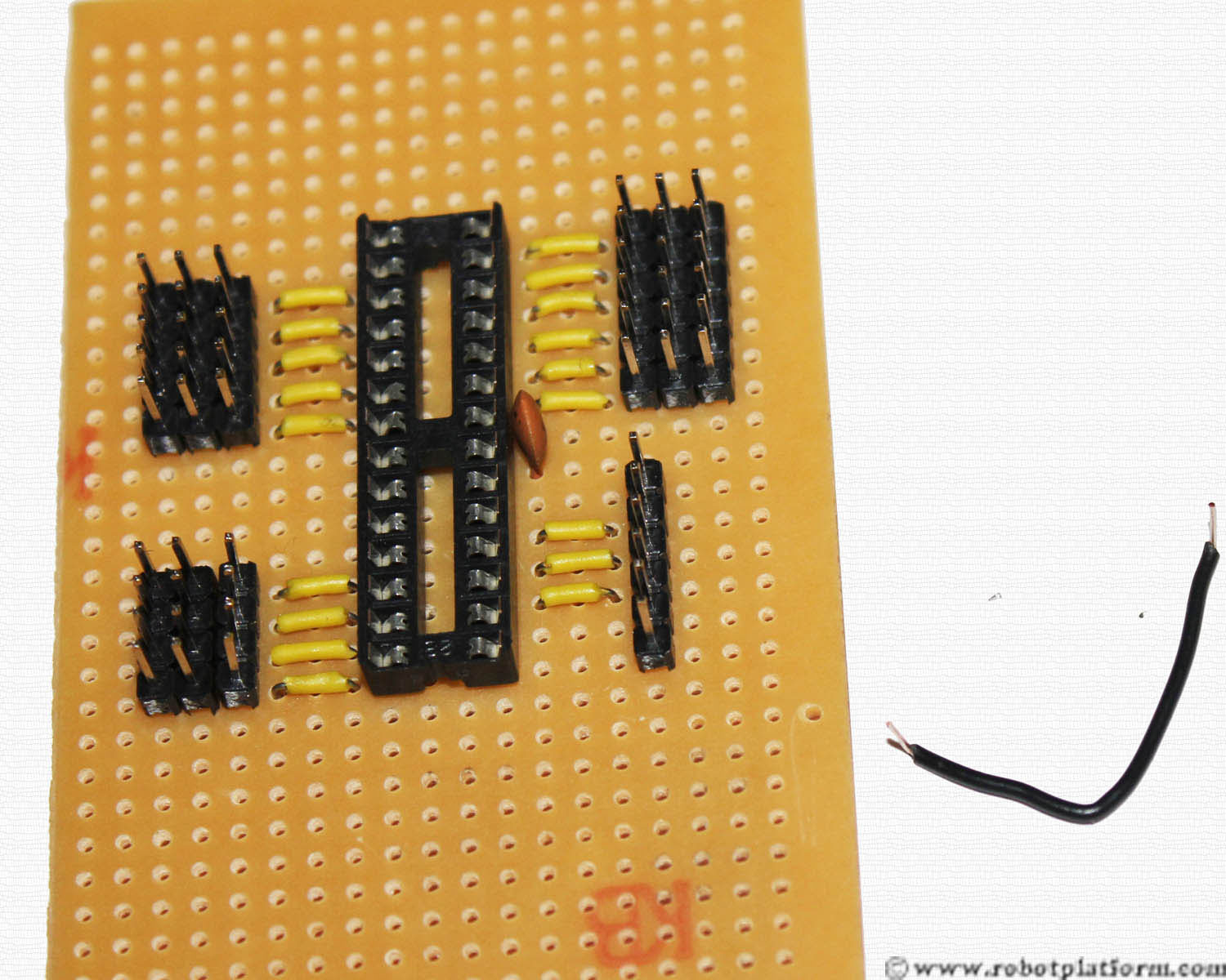
We are almost half done. Now add a 6 pin header to the right side of the board; exactly in the same column you previously added the signal headers. These pins are used to connect the programmer to the board. The first pin of the header should stay in the same row as PIN-20 of the socket and last pin of the header should stay in the same row as PIN-15 of the socket.
Note: I have used a 6 Pin ISP programmer. The pin-outs of the programmer used are as follows:
- Reset
- SCK
- MISO
- MOSI
- Gnd
- Vcc
If you have any other programmer, you can add connectors and plug them in. With a bit of technique, you can even add the specific number of pins into this board and solder the rest. If in doubt, let me know and I will try to help.
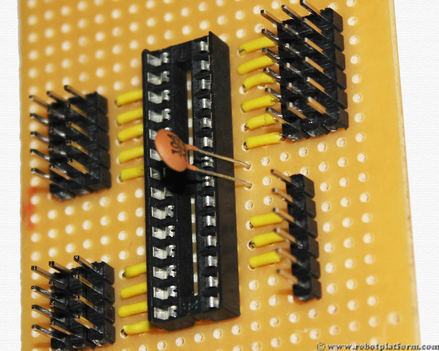
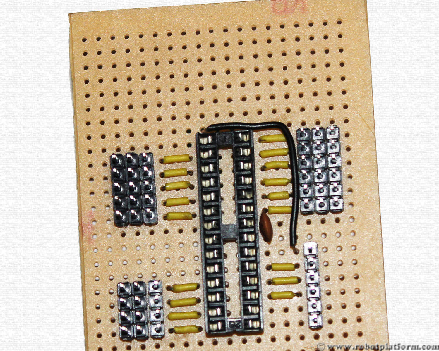
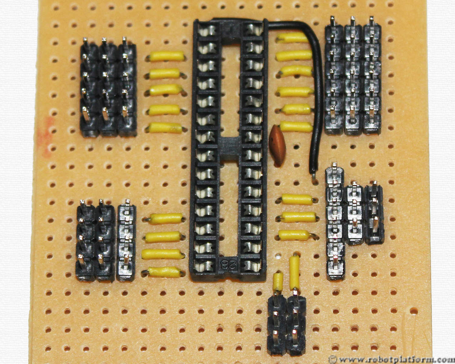
Now insert three more wires (hope you have cut and bent enough wires; if not do it now) between the socket and the header. Observe in the image that I have left out the first pin in the header and started off from the second one. Also, the last two header pins are not connected; yet.
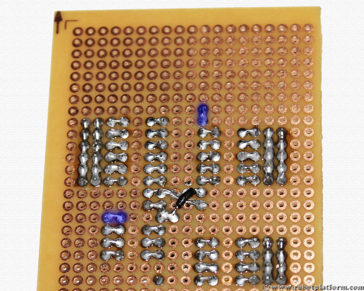
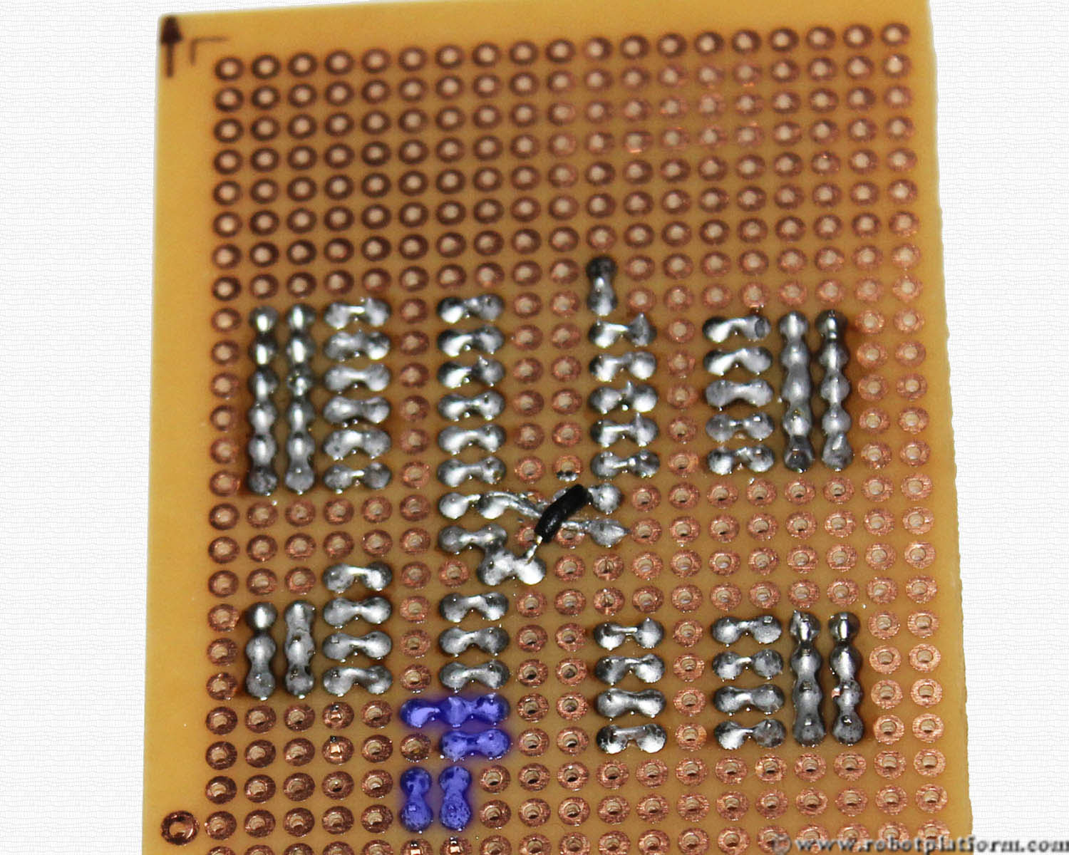
Solder the wires from header to the socket just like you did it before. Solder only three wires; Rest of the pins will be connected later.
Now we will add a ceramic capacitor to the board. If you already do not know, capacitors operate as an electron storage bank. A ceramic capacitor is a two-terminal capacitor which is used in high frequency applications. These capacitors do not have polarity and you can connect the leads in any way you want
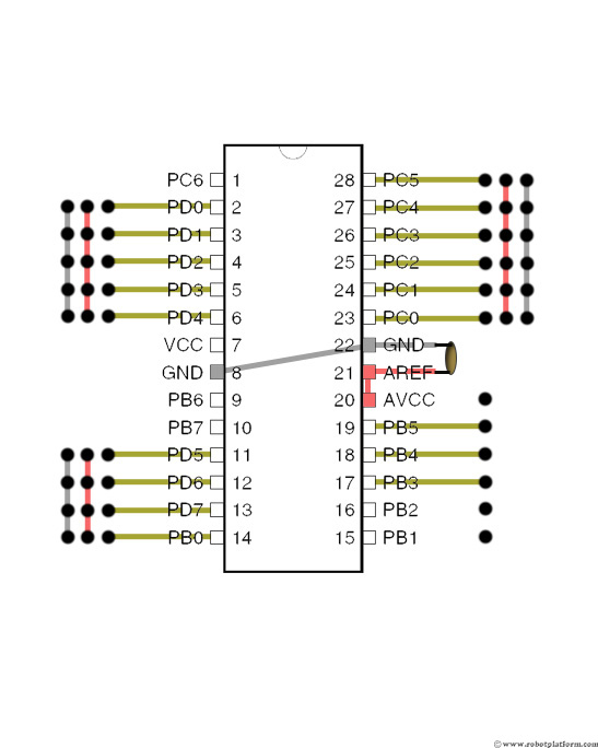
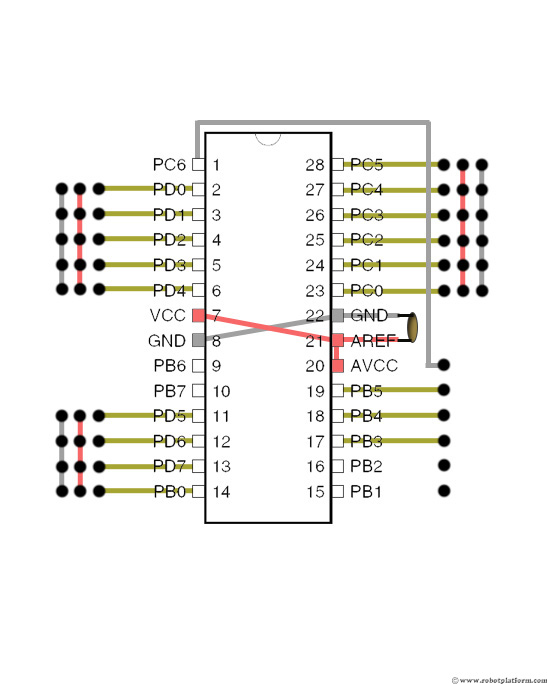
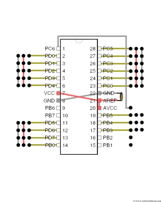
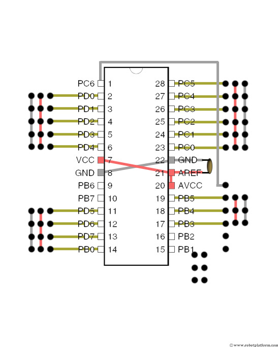
The leads go to the holes next to PIN-21 and PIN-22 of the socket. Keep the capacitor as close to the socket as possible. If at all you intend to build a high frequency application, you will understand why. For now, keep them close.
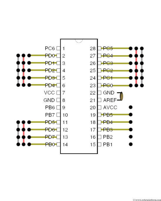
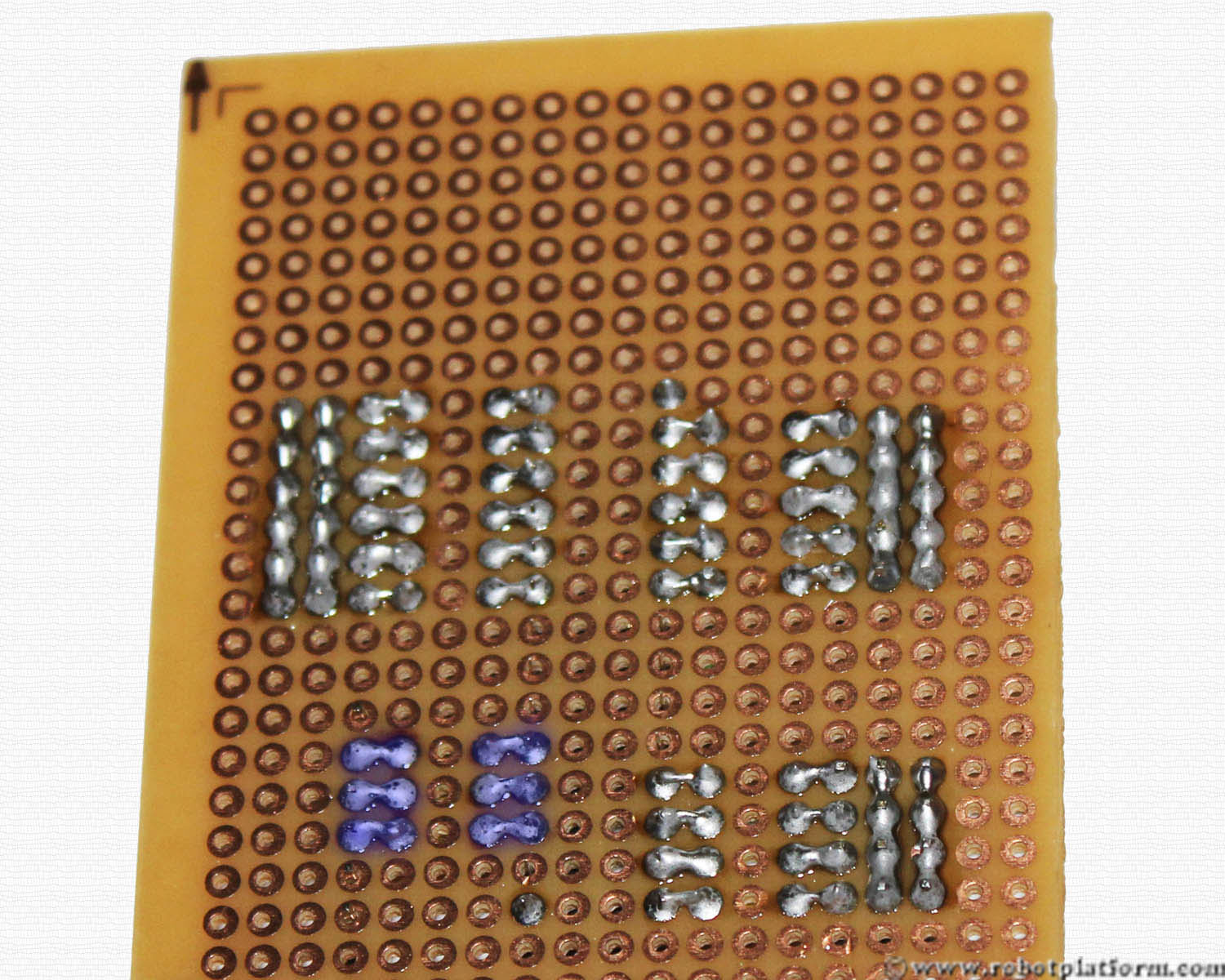
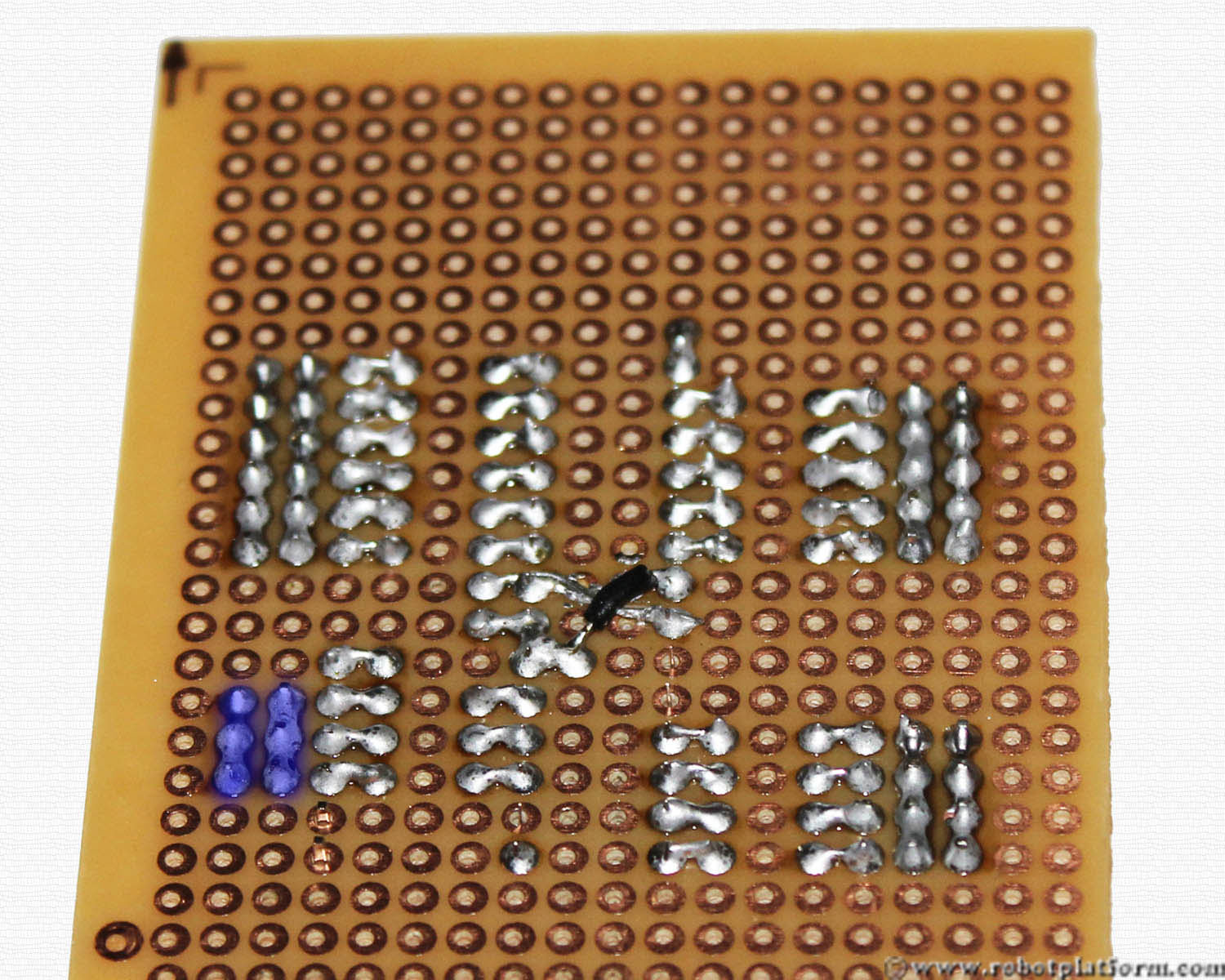
Soldering from now on gets a little tricky. Solder one lead of the capacitor to “Gnd”, i.e. Pin 22. Solder other lead of the capacitor to Pin-21 (which is AREF) of the microcontroller. (No. you will not plug the microcontroller yet. The names are given just for reference).
Now solder PIN-20 and PIN-21 together; i.e. you are soldering the two pins and a capacitor lead together.
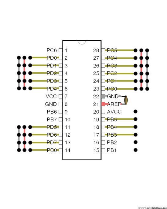
Trim one the leads of the capacitor, i.e. Cut off the extra lead of the capacitor connected to PIN-20 and PIN-21. Leave the extra lead connected to pin-22 as it is. We will use this lead to connect it further.
Bend the capacitor lead such that the other end reaches PIN-8 of the socket. What you are doing is connecting the ground (GND) pins together. Trim the capacitor lead if there is anything left over.
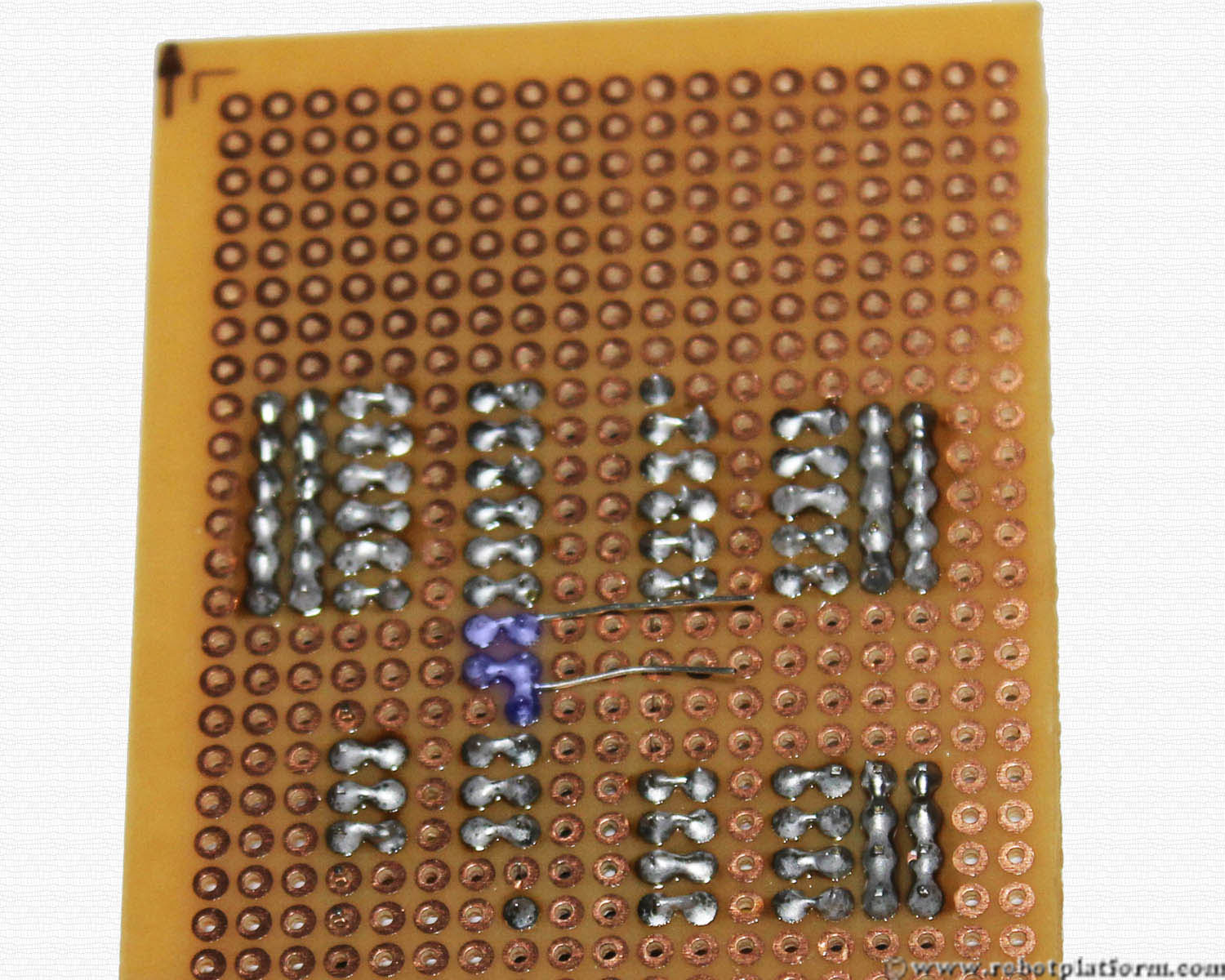
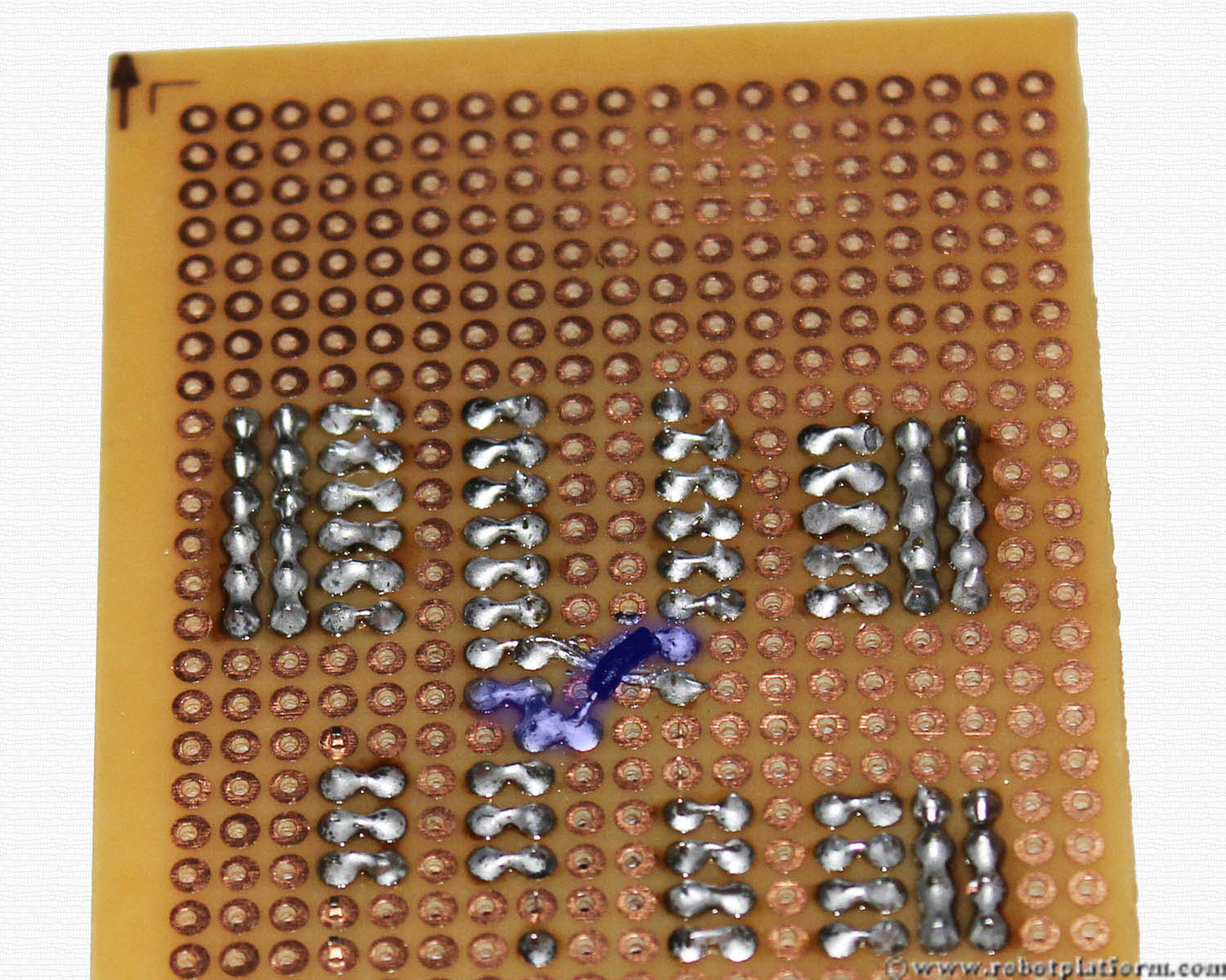
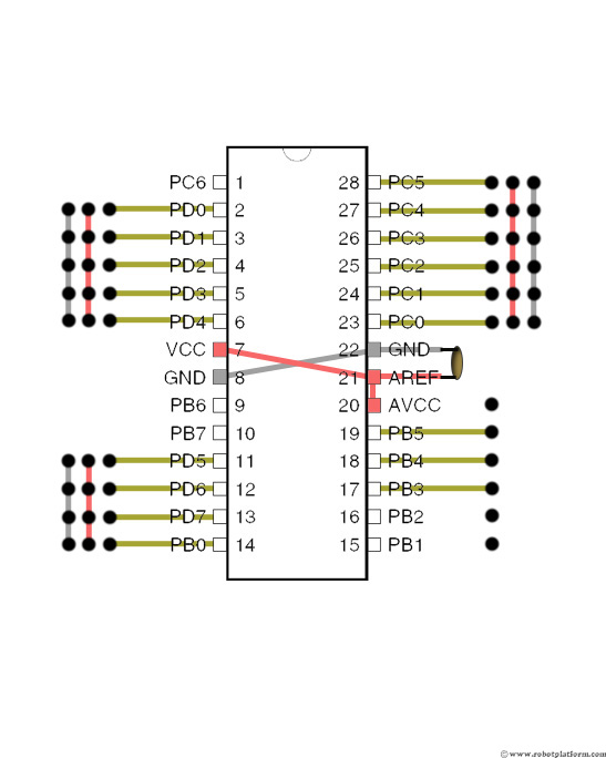
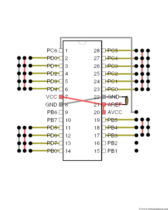
Now take another short wire and connect PIN-21 and PIN-7. What you are doing is connecting VCC and AVCC of the microcontroller. In this board I have used a black wire (was too lazy to cut a red wire). If you want to avoid confusion, you can use a red wire to indicate VCC. But, be careful not to short the capacitor wire (ground wire) beneth this connection.
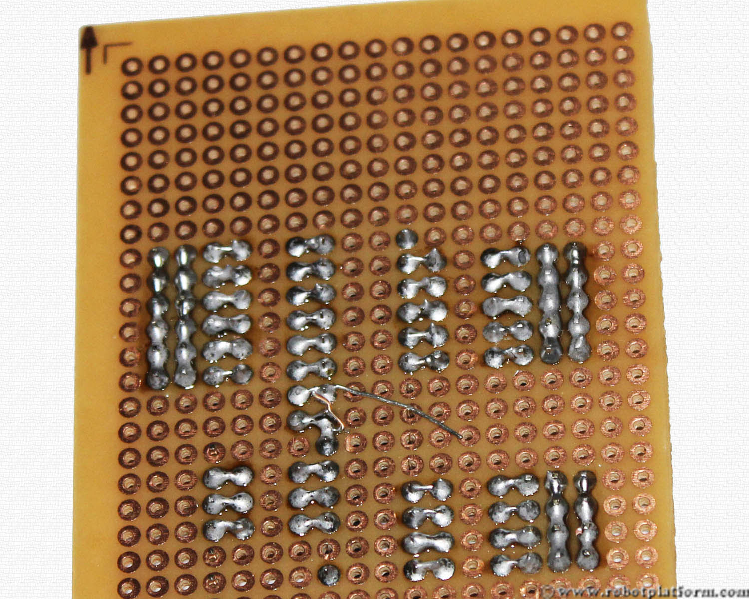
Take another black wire and bend it as shown in the image below. I have made an L-shaped wire which connects the programmer’s “reset” to microcontroller’s reset.
Connect one end to the first pin of programmer header (as shown in the image) and another end to Pin-1 of the microcontroller.
Solder the leads of reset wire as shown in the image.
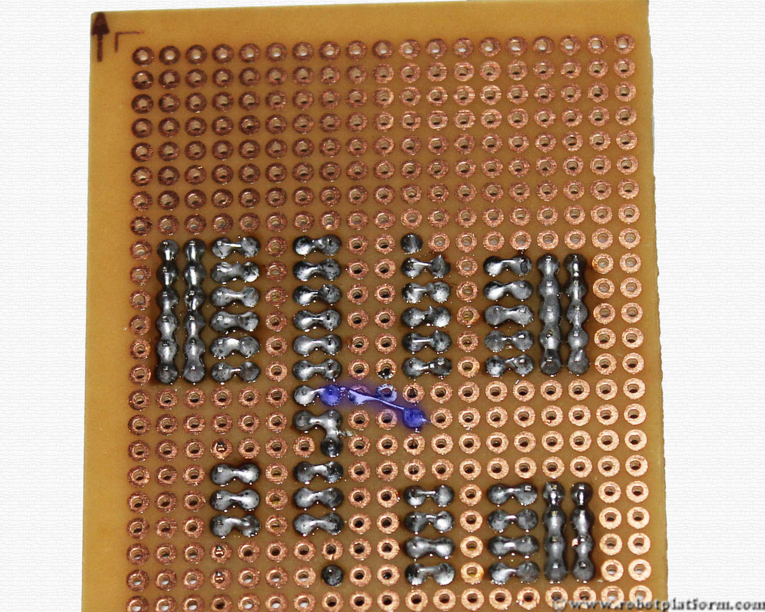
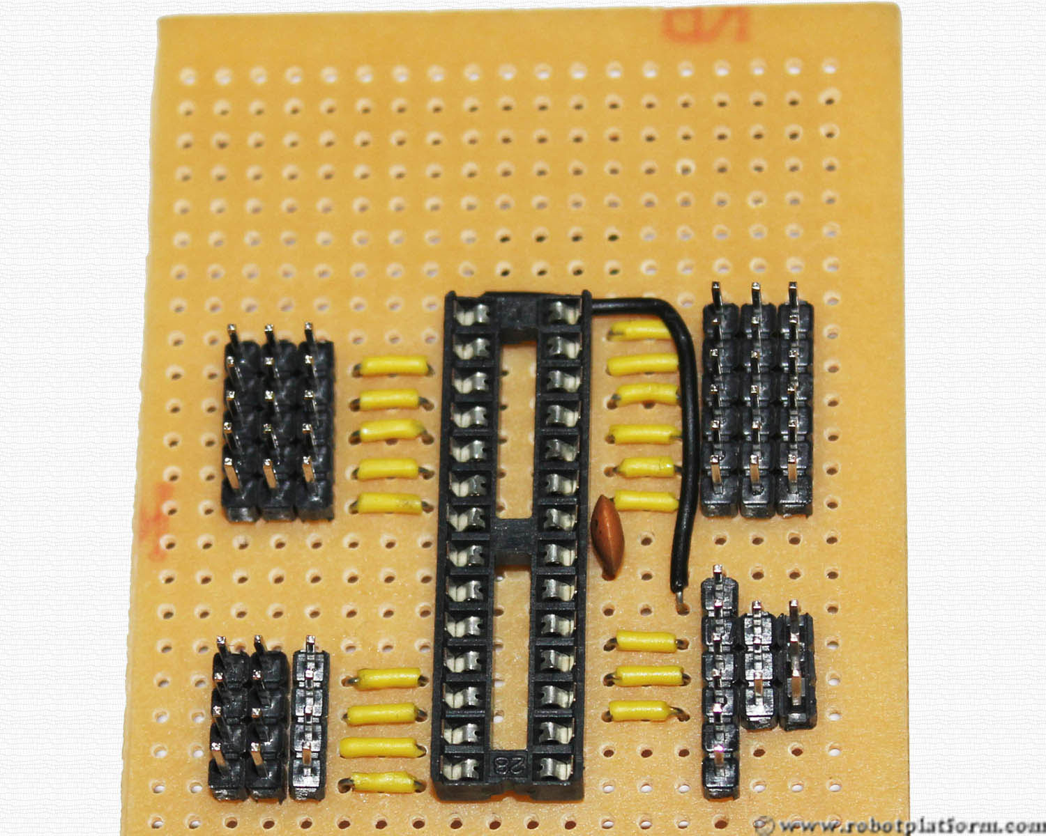
Add two more 3-pin headers next to the programmer, excluding the first programmer pin. We will connect ground and power lines to these headers.
Solder each header line as done before. Do not connect headers together, but solder all the pins in a header together.
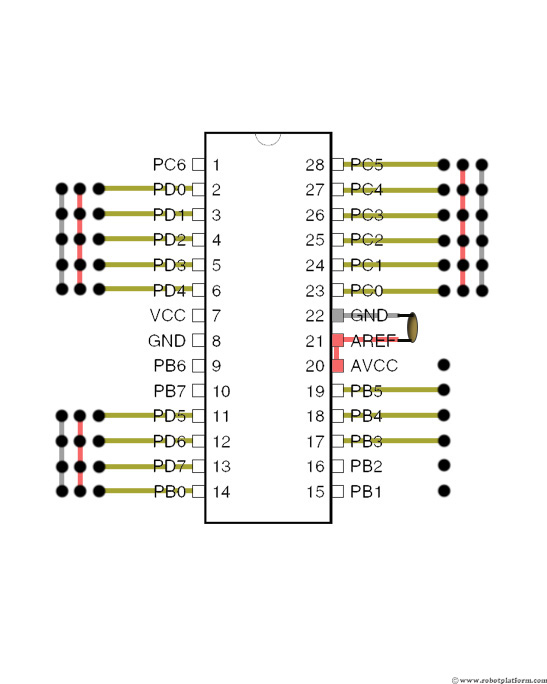
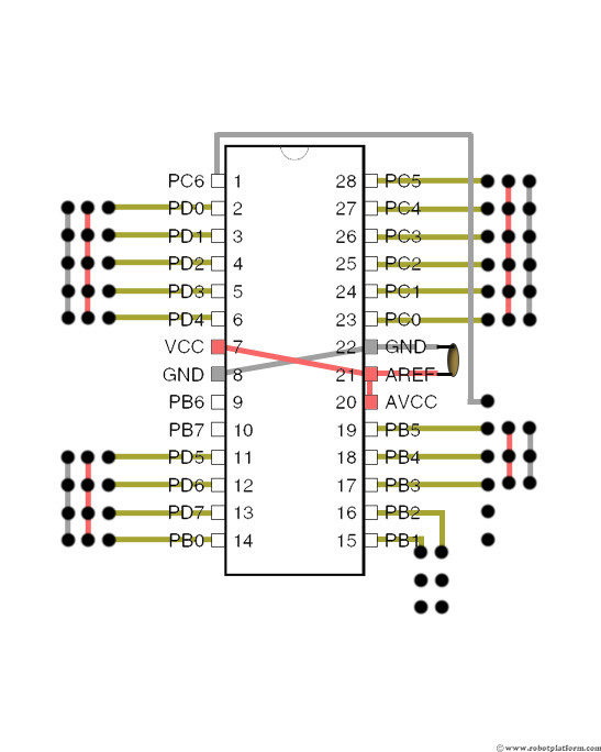
Now add 2 more three pin headers to the board. This is used to connect PIN-15 and PIN-16 of the microcontroller which are two I/O pins of PORTB. Few applications require timer/counter functionality and these pins are used for those serious applications. You may skip adding these pins, but why leave them off if you wish to build a complete development board at the cost of few additional headers.
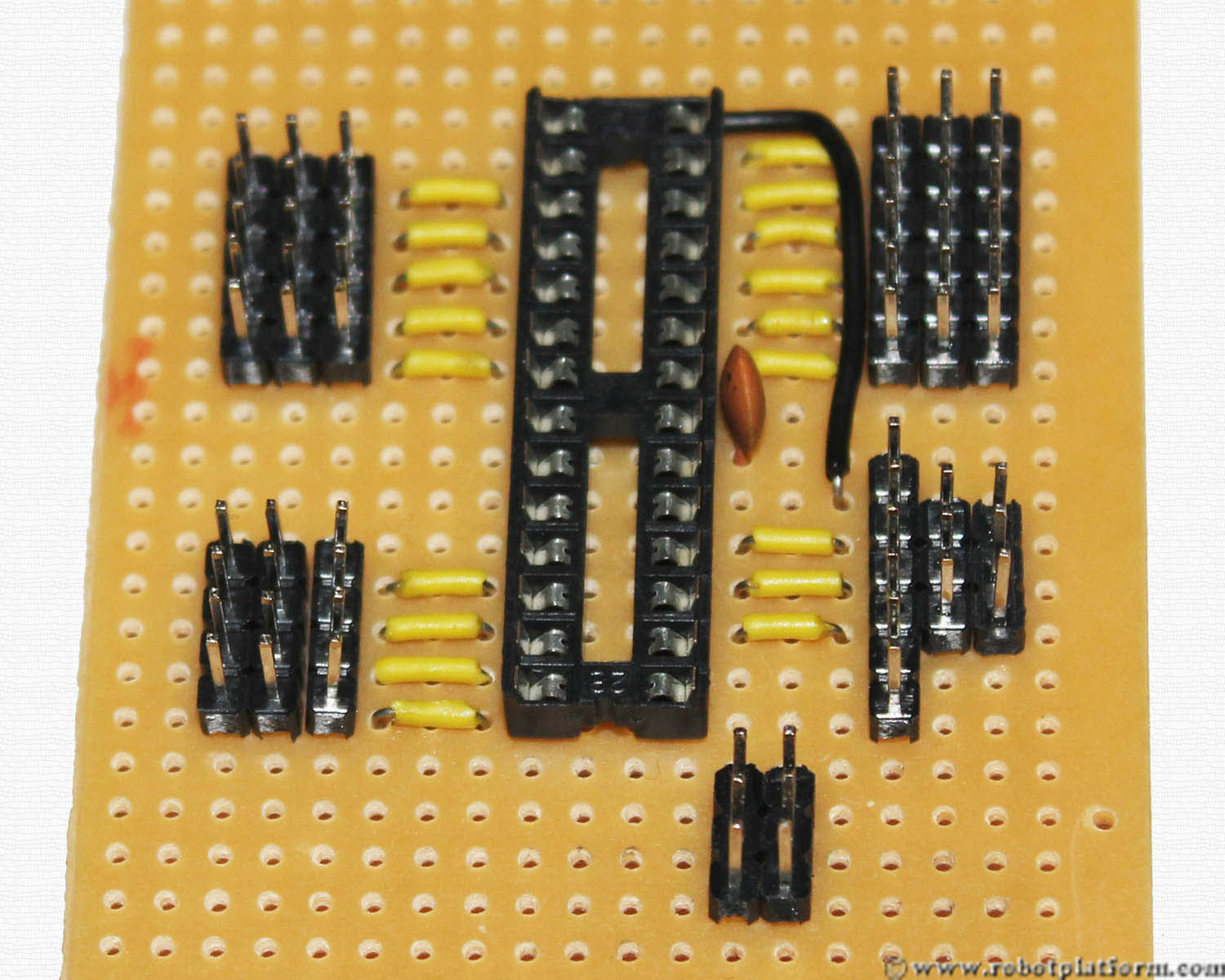
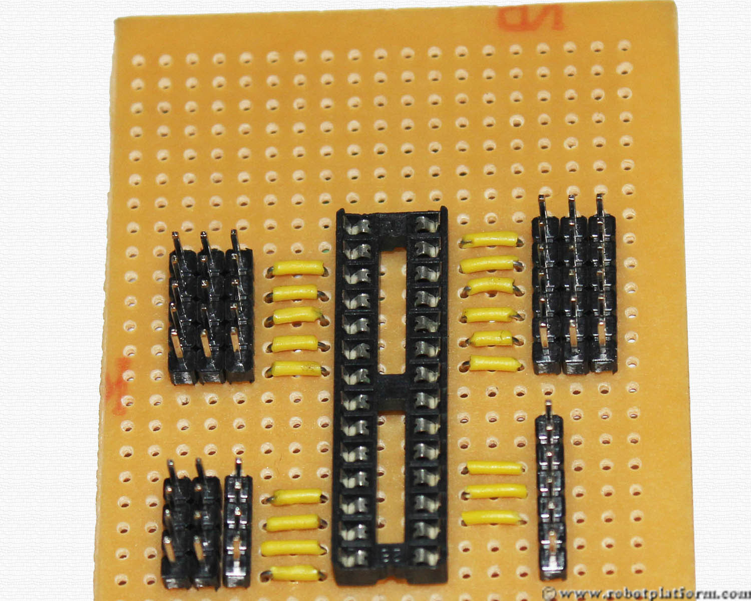
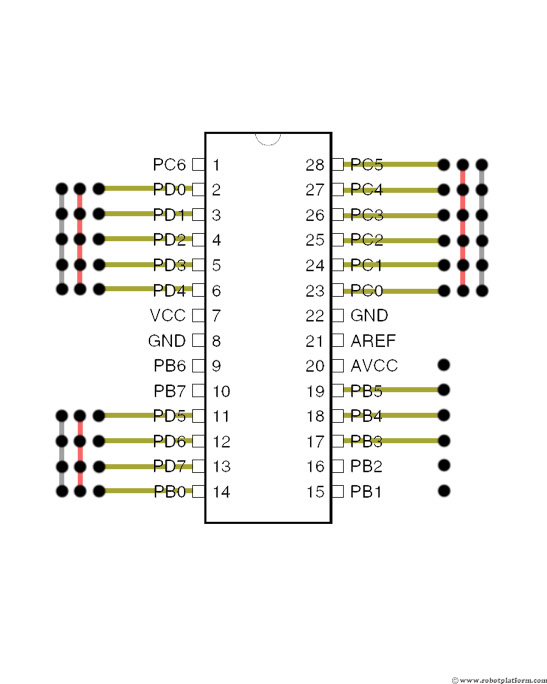
Push two wires into grids above the recently these headers. Observe that one of the wires is shorter and is plugged to the hole adjacent to PIN-15 (the bottommost pin of the microcontroller). The longer wire (right side) is plugged to hole adjacent to PIN-16 of the microcontroller. This is for PORTB, Pins PB1 and PB2.
Solder the wires as shown. These pins act as signal pins which are connected to PIN-15 and PIN-16 of the socket (microcontroller).
Tutorial index:
Do you have anything to say?
Visit the Forum to discuss, learn and share anything related to robotics and electronics !!


