AVR Development board, Step-by-Step-Tutorial
How to build an Atmega8 development board
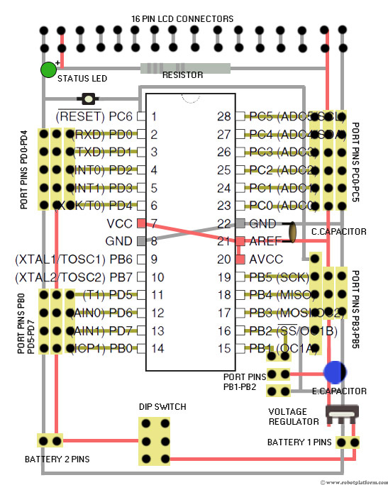
LCD headers (Optional)
This step is optional and works only if you have exactly followed the tutorial. The headers and grids are planned in such a way that from left to right, there are exactly 16 grids. If you have opted for a smaller board or if you have skipped / saved a few grids, stop here; there is no use going further.
Note: You can still use a separate LCD module by connecting wires from LCD module to this board. What really happens in the following part of this tutorial is help you save a few wires to make things compact.
Few things to keep in mind before attempting this:
- The power line (5V) and ground line will be connected to the first two and the last two pins of LCD header, which is your only saving,
- Your battery should be powerful to run both the board and LCD module. If you are using anything less than 1000mA, it may not work as expected.
- Even though you use this, you still need to use command and data lines separately by connecting additional wires.
If you are fine with the points mentioned above, well, follow the steps below.
Add a 16 pin male header just above the status LED and resistor
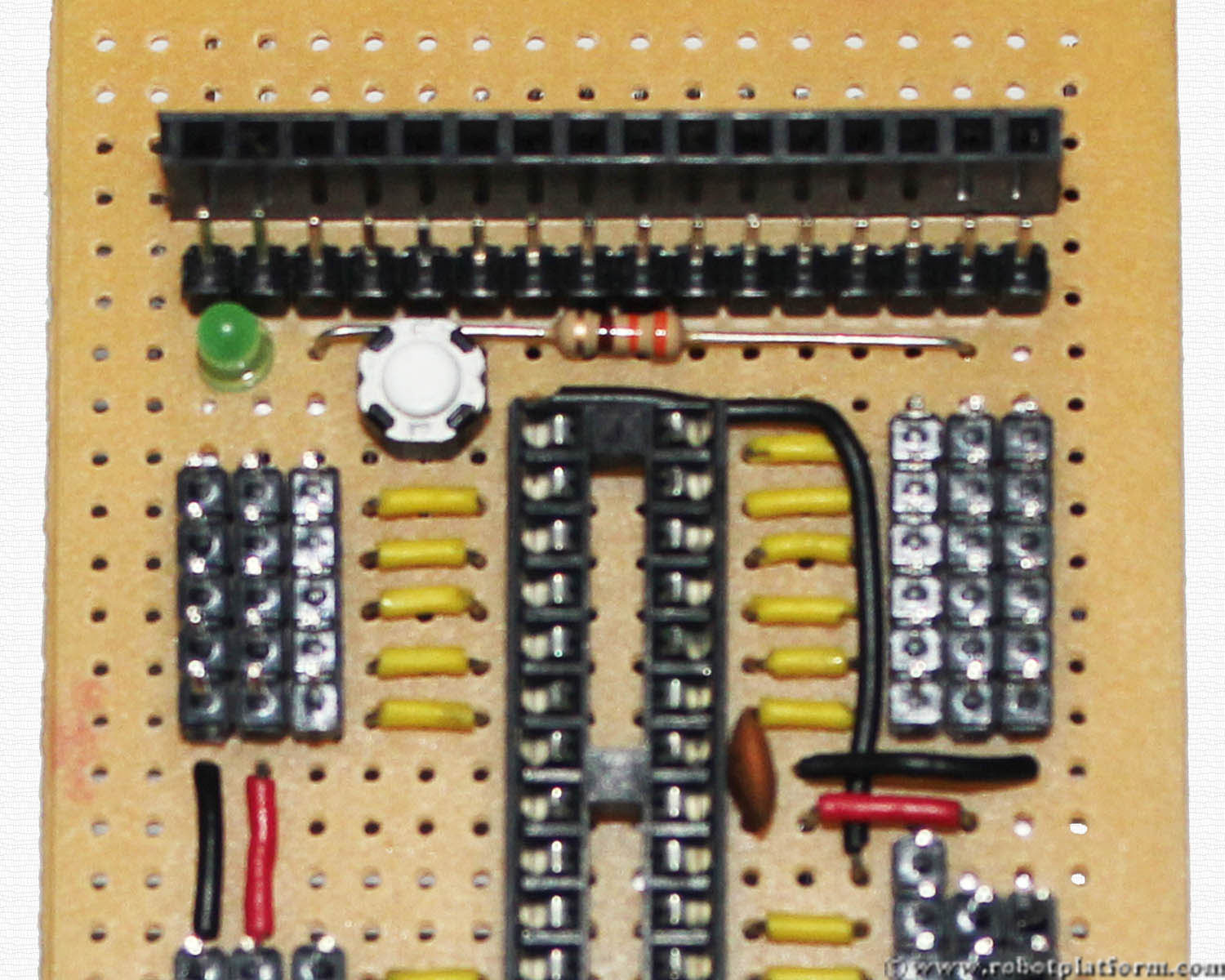
Solder the first and last two pins in the same line. That means power and ground lines are connected to either sides of the LCD module.
As a last step, connect each pin in male header to each pin of female header. This can be later used to plug in a general purpose alphanumeric LCD module with 16 pins. Trim the remaining leads from LED.
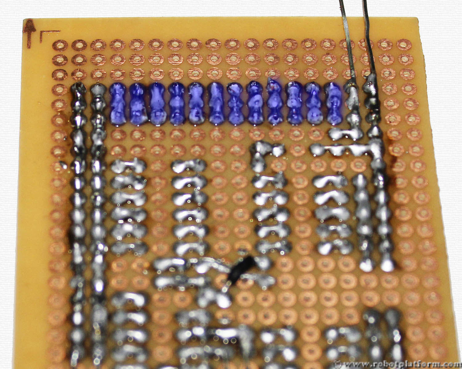
You now have an atmega8 development board with an LCD connector too.
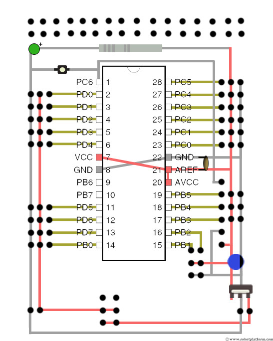
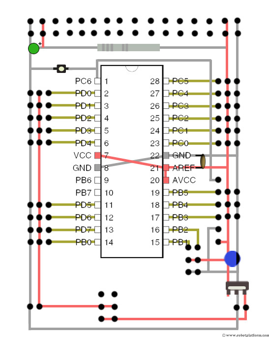
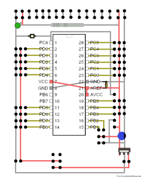
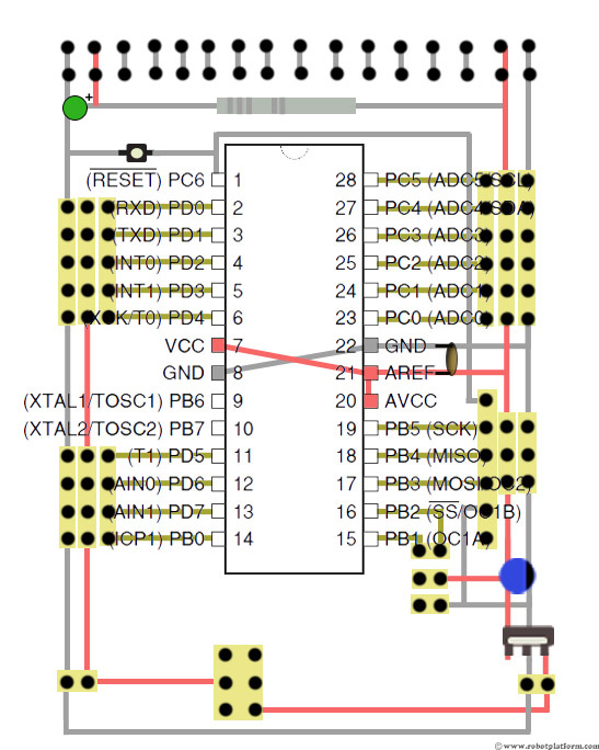
The next two images shows Atmega8 development board schematic. This schematic is my way of representing connections so that it is easier for a beginner to learn rather than faint looking at those complicated diagrams.
What if things don’t work as expected?
Well! Then say goodbye to soldering and robotics :)
It is actually rare that something works on the first try. So, what could be the problem? First of all, verify if you have followed the tutorial exactly as is. Then, pull out your Multimeter and check for connectivity; Check if you have soldered in the wrong places or left off at the right spaces. If all else fails, drop a line in the forum and you will find help. 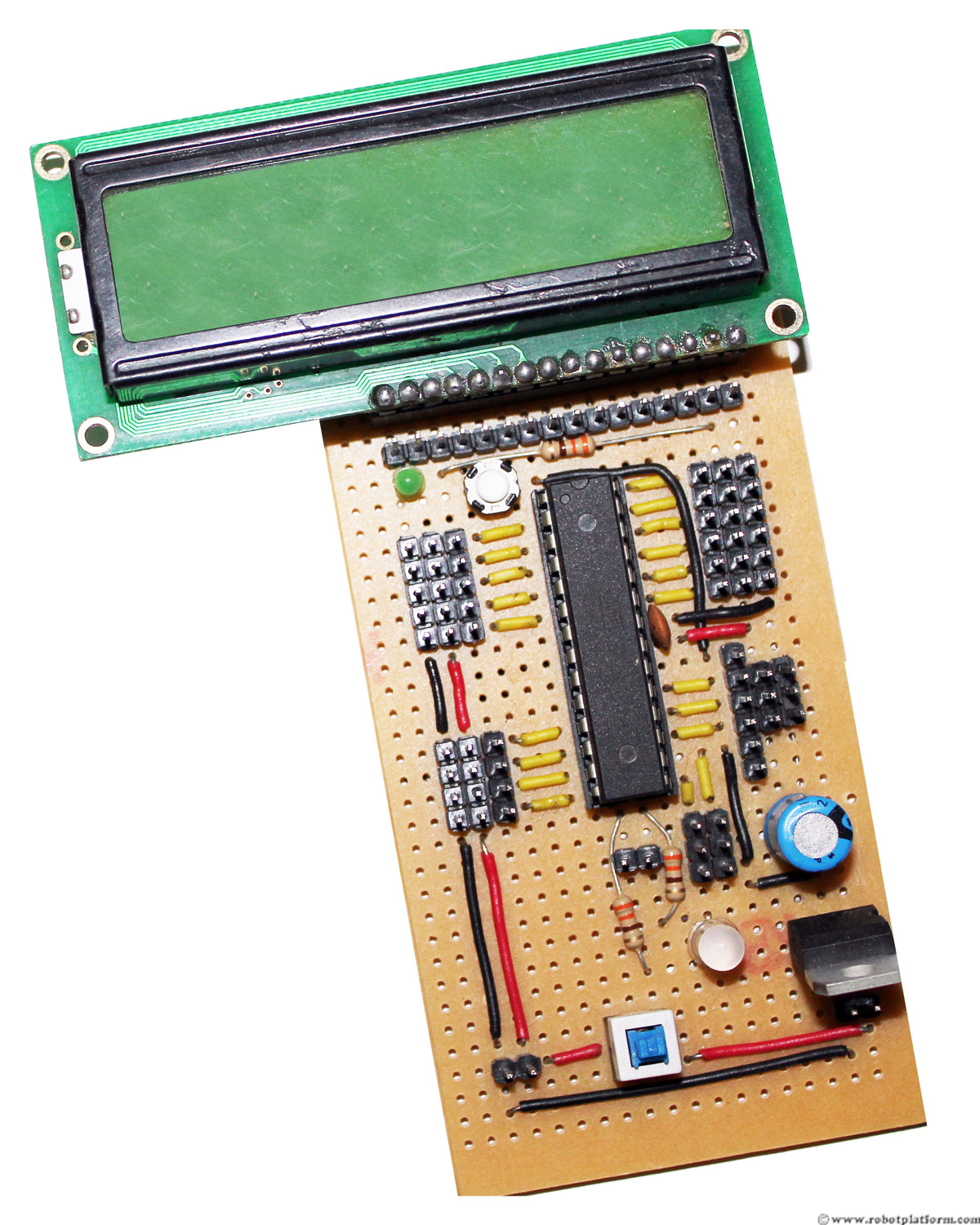
Note: You can see one more LED inserted and connected if you have observed the first image. That was added for a project of mine and it creates more problems than smiles. But if you are seriously unhappy for not telling you how, then here is the description. The LED connected is a dual color LED connected to two additional pins next to it. When an application asks for, I can pull two wires from the microcontroller and connect it. The drawback of this LED is that a "low" on the LED pin drives it on and a high drives it off, which is normally the other way in most applications.
Word of caution: Follow the above tutorial at your own risk. Take necessary precautions like wearing eye protection, gloves etc.
What next?
Next you can plan for a robot. Use this development board as a brain and show off to your friends and be proud. There are still few more additions left for this board and will update the tutorial with more add-ons. Enjoy.
Tutorial index:
Do you have anything to say?
Visit the Forum to discuss, learn and share anything related to robotics and electronics !!


