Electronics:
The Power of a microcontroller is its Pins and Ports by which it communicates with the external world. In the figure below, you can see a pictorial representation of an ATmega8 microcontroller.
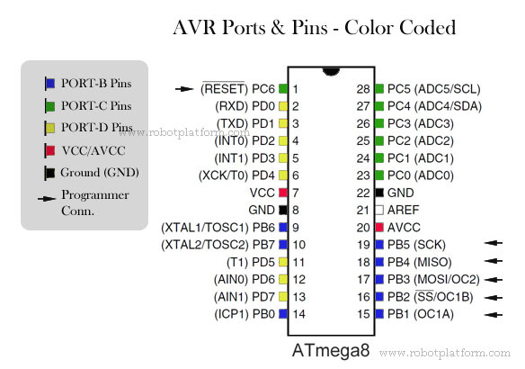
 Atmega8 has 3 ports PB, PC and PD. PB & PD (short for Port-B and Port-D) has 8 pins associated with it. PC (Port-C) has 7 pins associated with it. Few AVR variations can have as few as 3 pins in a Port.
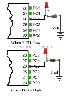
For this project, we will use Port-C (Green color coded). If the voltage in any pin (PC0-PC6) is set to High (5 Volts) and connected to positive lead of LED in series and further connected to ground, your LED should turn on. Set it to Low (0 Volts) and your LED should turn off.
On the other hand, if you connect negative lead of LED to Port Pin in series and further connected to 5 volts, then the LED turns on. Set the Pin to High (5 Volts), your LED should turn off.
This concept is simple. In the first scenario, current flows from Pin to LED to ground. In the second scenario, current flows from 5V power line to LED to pin, which is 0 volts. This is all the electronic knowledge required to turn on, or off a LED. Since I mentioned that entire port will be high, or low, you can connect the LED to any of the Pins in Portc.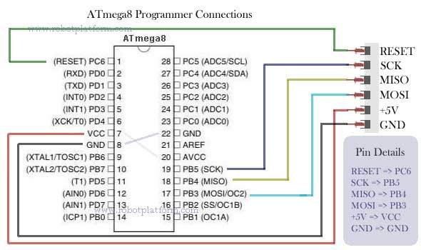
But how do we connect these electronic components together? For the LED tutorial, let us take the KISS approach. i.e. Keep It Simple & Stupid! We will use a breadboard, couple of wires, battery, LED and a programmer. No soldering, no burning. The circuit may look like a complex set of irregular connections. Refer to the figure in the right for programmer connections, or the Schematic
Tutorial index:
Do you have anything to say?
Visit the Forum to discuss, learn and share anything related to robotics and electronics !!


