Wheel Control Theory
In the previous section you have seen the different types of wheels and their arrangements. Once you have decided on how many and what type of wheels your robot will have, you need to put in a plan on how to control them. Below described are few control mechanisms to drive and steer your robot.
Differential Drive/Differential wheel: This is the most common control mechanism for robot builders, especially for beginners. The concept is simple; Velocity difference between two motors drive the robot in any required path and direction. Hence the name “Differential” drive. Differential wheeled robot can have two independently driven wheels fixed on a common horizontal axis or three wheels where two independently driven wheels and a roller ball or a castor attached to maintain equilibrium.
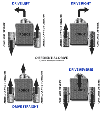
There are three fundamental cases which can happen in a differential wheeled robot:
- If the angular velocities are identical in terms of both values and direction, i.e. if both the wheels are driven at the same speed and same direction (either clockwise or anticlockwise) then the robot tends to spin around its vertical axis. This complete turn capability is one of the greatest advantages of a differentially driven robot (a.k.a zero radius turn).
- If the angular velocities are identical in terms of values and opposite in direction, i.e. if both the wheels are driven in the same speed but in the opposite direction (One clockwise and other anticlockwise) then the robot is more likely to follow a linear path, either forward or backward based on the motors spin.
- If the angular velocities are different in terms of values (same or different direction), i.e. if the wheels are driven at different speeds in the same direction or opposite direction, then the robot makes a curve motion. Lastly, if one of the wheels rotate and the other stays still then the robot almost makes a 90° turn. Manipulating the drive speed and direction can give some interesting drive paths.
Design, mechanical construction and control algorithm can never get any simpler than this driving technique, and the concept can be incorporated in almost any kind of robots including legged robots.
One of the major disadvantages of this control is that the robot does not drive as expected. It neither drives along a straight line nor turn exactly at expected angles, especially when we use DC motors. This is due to difference in the number of rotations of each wheel in a given amount of time. To handle this problem, we need to add correction factor to the motor speed. For example if you intend to drive your robot in a linear path and feel that the robot is turning towards one side, then a correction factor can be added to reduce the speed of the other wheel.
The better option is to use dual-differential drive which can mechanically guarantee straight line motion. In this approach, each wheel has mechanical differentials and differentials combine the forces from shafts and drive the wheels. In other words, two wheels are connected to two motors where one motor controls the rotation of both wheels while the other controls the direction. Few robot builders have implemented 3L differential drive; since is it not very popular, and the results are not in any way far better than dual differential drive, we can happily skip that for the moment.
Skid steering is another driving mechanism implemented on vehicles with either tracks or wheels which uses differential drive concept.
Most common Skid steered vehicles are tracked tanks and bulldozers.
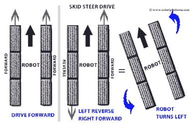
This method engages one side of the tracks or wheels and turning is done by generating differential velocity at opposite side of a vehicle as the wheels or tracks in the vehicle are non-steerable.
If you have understood differential drive concept, there Skid steering is no different. In differentially driven robot, there is a castor which balances the robot and in Skid Steer drive, the castor is replaced with two driving wheels. Suppose you need your robot to turn left; then the right wheels or tracks are driven forward and the left wheels or tracks are driven backward until the robot turns right. If the drive continuous in the same way, then the robot will have a 360° turn with almost 0 radius. Suppose if there are four wheels attached on each side, then the front and rear wheels rotate more and the center wheels almost skid to turn. Thus the name Skid steer.
Some of the advantages of skid steer drive are:
- They have greater traction and especially good for rough terrain
- Same concept can be used on both tracked robots and wheeled robots
- Since there are no explicit steering wheels, steering mechanism is not required
- Since all wheels on each side drive in the same direction, only two motors are enough for driving and steering the robot
- This method does not require castor wheels and hence eliminates the problems caused by castors
Few drawbacks of Skid steering are:
- Since it uses skidding or slipping technique, increases wheel / track wear reducing life
- Like differentially driven robots, driving in a straight path is a hard to achieve task as both the motors are expected to drive at exactly the same speed. This can still be taken care by other sensing devices, but adds cost and control mechanisms.
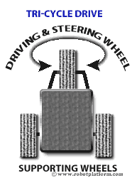
Tricycle Drive: For robots with three wheels a tricycle approach can be used. If you have seen a tricycle, then you already know how to design this. Tricycle robot is designed with a front steering wheel controlled by a motor. The two rear wheels are attached to a common axle driven by a single motor with two degrees of freedom (either forwards or reverse). The disadvantage is that they cannot spin like a differential drive robot and does not have a 90° turn due to their limited radius of curvature. Few robots have both steer and drive controlled by the front wheel and the rear wheels act as supporting wheels to maintain equilibrium. Due to the design constraints and its drawbacks, this design is less appreciated by the robot building community.
Ackermann Steering: One of the most common configurations found in cars is Ackerman steering which mechanically coordinates the angle of two front wheels which are fixed on a common axle used for steering and two rear wheels fixed on another axle for driving. 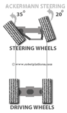
The advantage in this design is increased control, better stability and maneuverability on road, less slippage and less power consumption. This might resemble the tricycle approach where the front wheel is replaced with two wheels and an axle. But when two wheels are attached to a tricycle design (axle-articulated drive), then turning causes the robot to skid. To overcome that drawback Ackerman steering is designed in such a way that when there is a turn, the inner tire turns with a greater angle than the outer tire and avoids tire slippage. This approach can be generally used for fast outdoor robots which require excellent ground clearance and traction. Although there are disadvantages, the downside is additional parts required; no zero radii turn and increased complexity in design.
Note: The angle mentioned in the image is just to make it easier to understand. If you decide to use this, make your own research and calculations.
Synchronous Drive: For even surfaces, this design can be considered the best as the navigation is very precise. 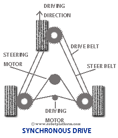 It can be constructed with three, or four or any number of wheels, but all the wheels should be in unison and turn together in the same direction and at the same speed. More than three wheels would mean additional complexity and hence this method is best for robots with three wheels on an even surface.
If you would like to build a robot in this design, then you can connect all the wheels by a single belt and further to a single motor. This means the single motor decides the speed of all three wheels. A second motor can be used to spin these connected wheels around their vertical axis, steering them.
If you are planning to build a kitchen robot, then this approach might very well interest you. RWI’s B21 robot uses a similar approach.
Omni Directional Drive: Omni directional robots are built using Omni wheels and/or castors. Since Omni wheels have smaller wheels attached perpendicular to the circumference of another bigger wheel, they allow wheels to move in any direction instantly. The major advantage is that they do not need to rotate or turn to move in any direction unlike other designs. In other words, they are Holonomic robots and can move in any direction without changing the orientation.
Omni wheels are available in many different varieties classified on their size, diameter, design, size of smaller wheels attached etc.
Omni-wheel Design: 3 Wheels vs. 4 Wheels
Generally Omni wheeled robots use either a three wheeled platform or a four wheeled platform. Each design has its own advantages and disadvantages.
Omni Wheels – 3 Wheel vs. 4 Wheel design
3-wheel design: A three wheel design offers greater traction as any reactive force is distributed through only three points and the robot is well balanced even on uneven terrain. This design also reduces an additional wheel compared to a 4 wheeled robot which makes it cost effective (yes, these wheels are expensive). In few instances, I have see that designing a three wheeled Omni robot is simpler and can drive more straight than a four wheeled robot, although I would still vote for a 4 wheeled robot. 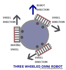
Few designers add two wheels parallel to each other and one wheel perpendicular to the two wheels which is a better design or a compromise between three and four wheeled Omni-drive robots.
3-wheeled Omni robots come with their own disadvantages. First from the design perspective, since the wheels are spaced at 120°, only one of the wheels will be 100% efficient; In other words, there is only one driving wheel and two free wheels which make it drive at lower speed. The next major annoyance is with the calculation. Since none of the wheels are aligned in the same axis, it requires 3 different calculations for 3 wheels.
4-wheel design: In 4 wheel design, 4 Omni wheels are attached at 90° to each other. This means any two wheels are parallel to each other and other two wheels perpendicular. The first and the major benefit is the simplified calculation. Since there are two pairs of wheels, each pair requires only one calculation and all four wheels require only two calculations. Also at any point there are two driving wheels and two free wheels. This makes the two driving wheels 100% efficient and drivers the robot at higher speed compared to 3-wheel design.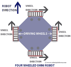
The only drawback which I have found is that a four-wheeled Omni robot does not balance on irregular terrain and also not all four wheels are guaranteed to stay on the same plane. Additional wheel might also pose an extra cost, but the advantage makes this seem a minor concern.
Both 3 wheeled Omni design and 4 wheeled Omni design require at least of two motors for minimum functionality; 3 motors and 4 motors respectively, if you require absolute efficiency. In spite of all the drawbacks, people still prefer to make 3 wheeled robots than 4 wheeled robots with Omni wheels.
Irrespective of three, four or any number of wheels Omni-wheeled robots have few drawbacks:
- Omni-wheels are expensive
- They are less efficient since not all wheels are fully utilized for driving and controlling the robot
- Since Omni wheels are a combination of many wheels / rollers into one, there is a greater resistance to rotation which leads to greater loss of energy; i.e. Loss due to friction.
- Since Omni-wheeled robot works on the principle of slippage, position control is difficult
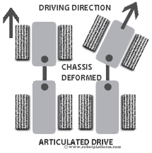 Articulated Drive: Similar to Ackerman Steering concept, Articulated method drives a robot by deforming the entire chassis or frame to turn instead of just the wheels. This is generally used for industrial robots where a four wheeled robot is split into two, the front part and the rear part which is connected by a vertical hinge. A motor or hydraulic system (generally) changes the angle of front part of chassis which turns the robot in a required direction and other motor drives it. This is a complex design which requires precise calculation of hydraulics or motors, but very useful for slow moving heavy duty robots. In some cases, only the axle is turned which makes it an axle-articulated drive.
Independent Drive: In this approach, each wheel is driven and controlled explicitly. 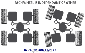 Suppose we implement this concept on a four wheeled robot, then each of those wheels can be driven and steered independently.The problem with this approach is coordination between the wheels since each wheel heads in its own direction. If coordination fails, it results in actuator fighting affecting the entire system. But if the coordination is achieved, then this approach is best suited for uneven and untested terrains. Even if one of the wheels get stuck, or stops working, then the remaining wheels can pull the robot to desired position and direction. The same concept can also be used on legged robots where each leg works independent of the other.
Which driving technique to use for my robot?
If you are a beginner in robot building, it is always good to select three to four wheels for your robot, and differential drive as the driving technique. If you have built atleast two to three robots, then choose between the different driving techniques depending on the enrivonment the robot is expected to work.
Do you have anything to say?
Visit the Forum to discuss, learn and share anything related to robotics and electronics !!


