Dual H-bridge Motor Driver - L293D IC
Parts required
| Parts | Details | Quantity |
L293D IC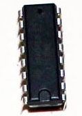 L293D Motor Driver IC |
Motor Driver IC | 1 |
16 Pin Socket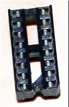 16 Pin Socket |
8x2 DIP Socket | 1 |
Perforated board 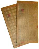 Perforated board |
With 20x12 or more holes | 1 |
Connecting wires  Wire |
Any color of your choice | 10-12 small pieces |
7805 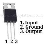 7805 |
Linear Voltage Regulator | 1 |
Male breakaway headers 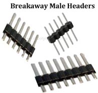 Male Breakaway Headers |
40 pin single row headers | 1 |
Solder  Solder Lead |
Lead / Lead free | 50-100 gms |
Solder Iron  Solder Iron |
Preferably temperature controlled | 1 |
Building the circuit - Part I
Before building the circuit, I prefer using DIY Layout Editor to replicate the circuit. DIY Layout Editor is a free PCB design tool which I would highly recommend if you are someone who works like me :)
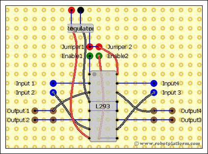
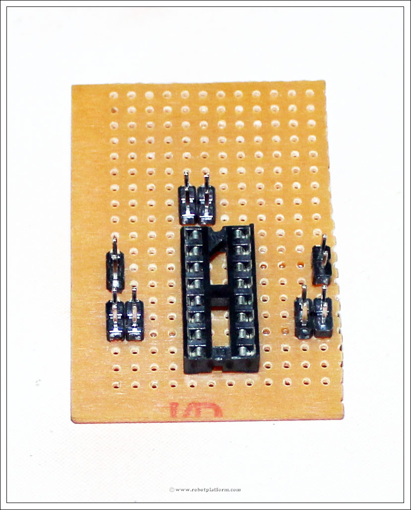
Let's begin building the circuit. First, add 16 pin socket to the board as shown in the image. As usual, click on any image for an enlarged view with higher resolution. If the step requires soldering, then the soldered part is highlighted to help you with soldering.
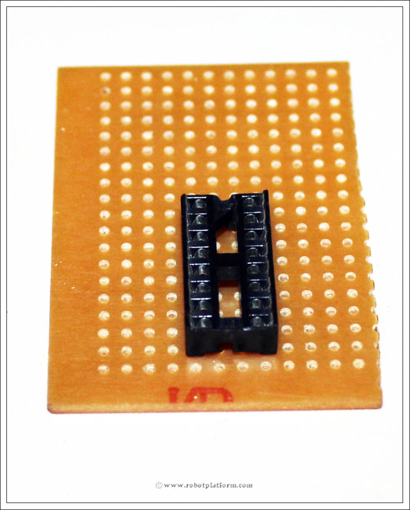
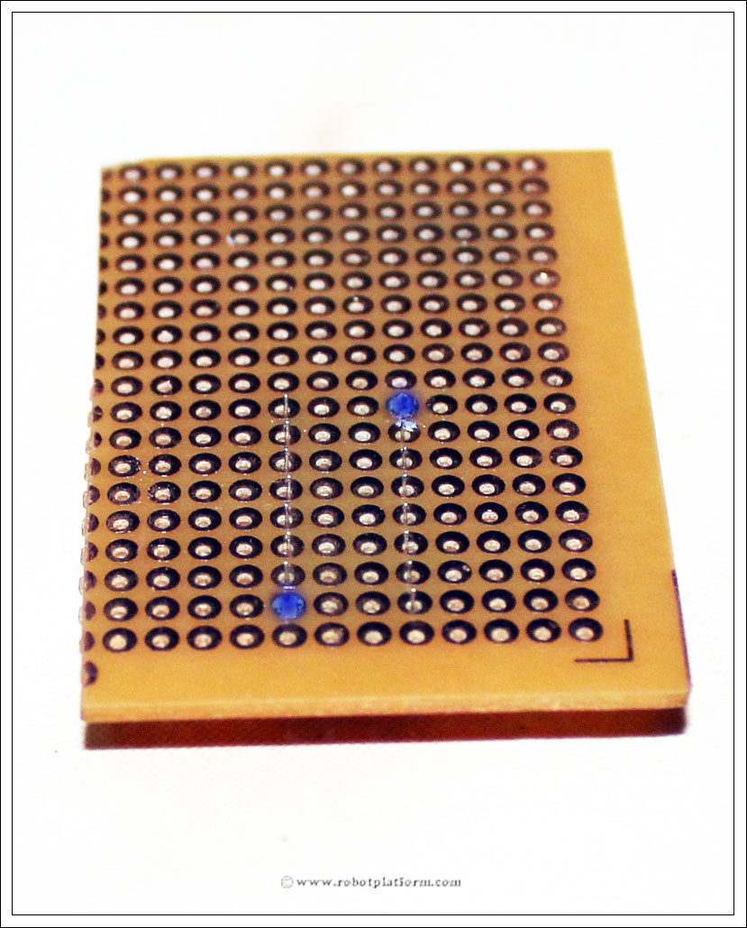
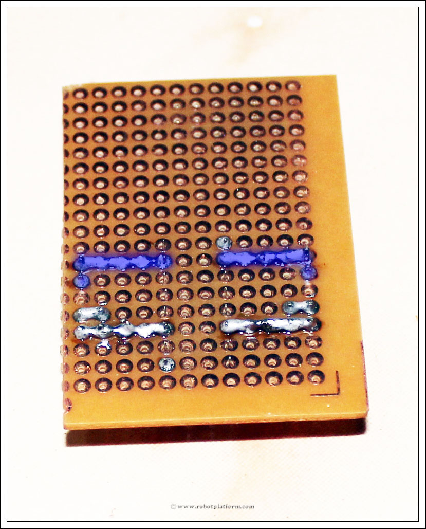
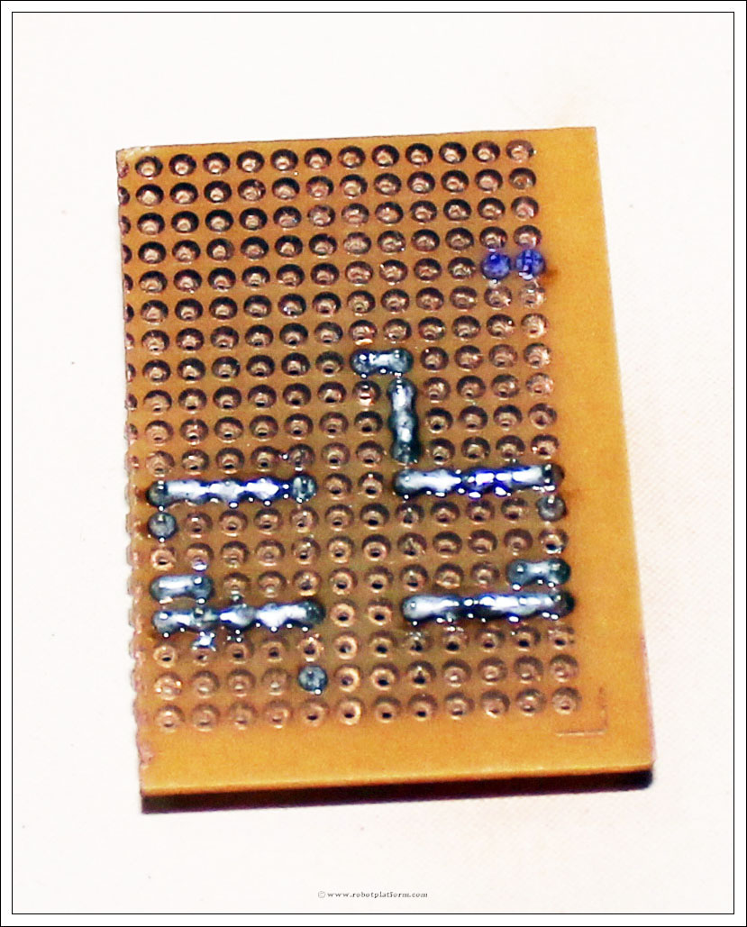
Solder first and 16th pin of the socket to copper side of the board.
Add two 2-pin headers (two 2 pin headers) to the left of socket. Make sure there is at least a gap of two holes between socket and header.
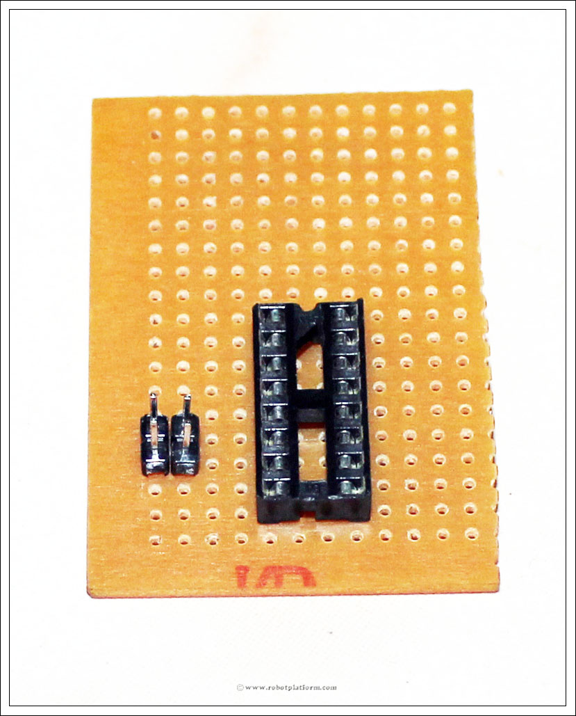
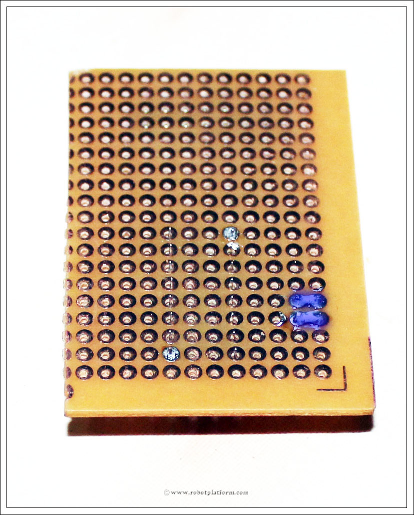
Solder horizontal pins together.
The vertical two pins will be later used to connect the first motor. The other two pins are there in case we need to use this output for some other reason. If you do not need this, you can use a single 2-pin header and plug it vertically and individually solder the two pins to the board.
Add two more 2-pin headers to the right side of the socket with a minimum gap of two holes between socket and header. The gap makes it easier to plug other female headers once the board is completed.
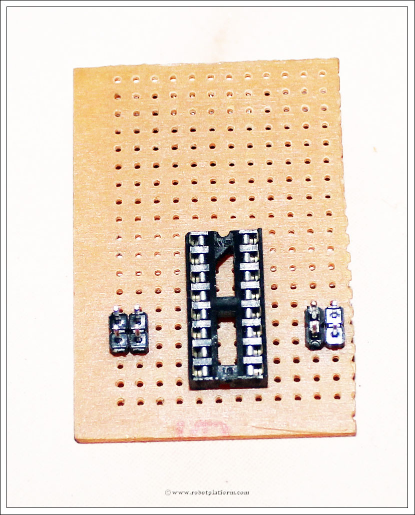
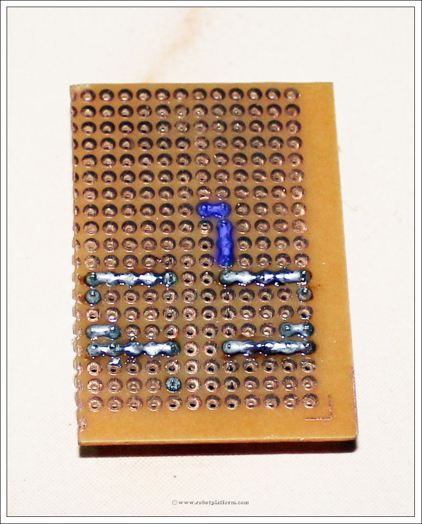
Solder these two headers similar to the left headers
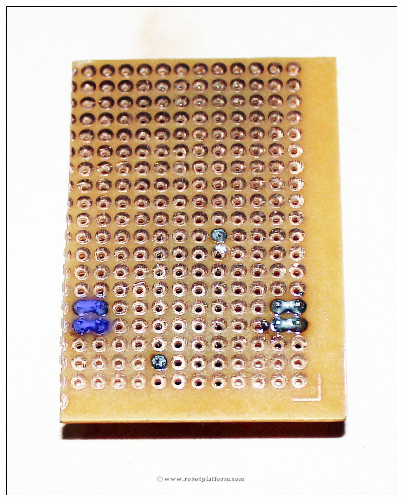
Now solder the bottom pins of two headers on either side to Pin6 and Pin11 of the IC, as shown in the image.
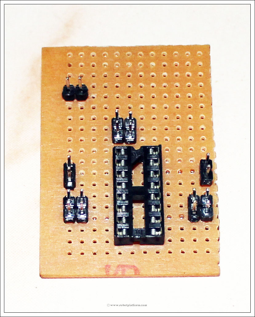
Add two more 2-pin headers to either side of the board. These two headers are input pins which are later connected to microcontroller.
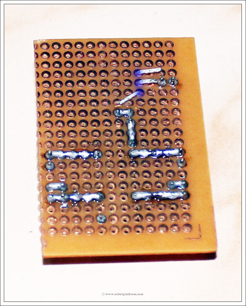
Solder each pin of the header to the board, but take care not to solder them together. As shown in the image, solder the top two header pins on either side to Pin2 and Pin15 respectively.
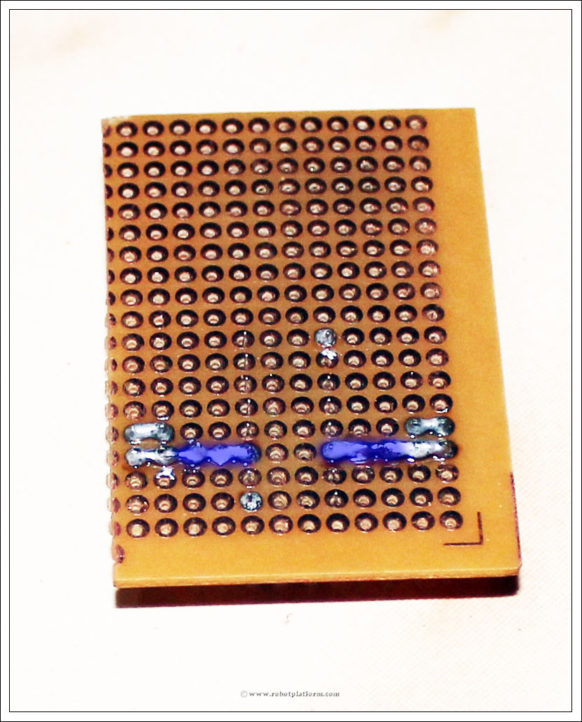
We need two more 2-pin headers, one header for enable pins and other for +5V. Push the two 2-pin headers as pictured below. Let the first two vertical pins be in the same line as the socket pins.
Observe carefully how the soldering happens from here on if you are not sure what is happening. I can assure that you would have a complete working circuit if you follow the tutorial exactly.
The top two header pins are soldered together. One of the pin in bottom header is soldered to Pin1 of the socket. Click on the image to understand what I mean.
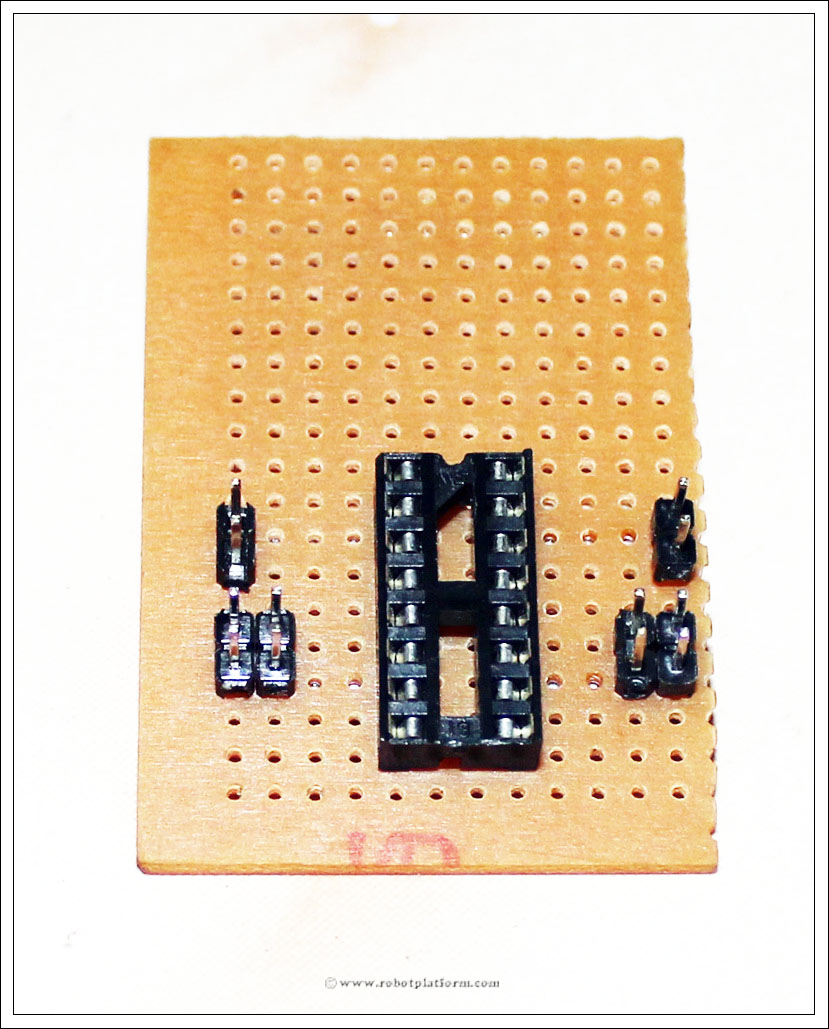
We will add two more pins for powering the circuit (we will call these two pins as Power pins to make soldering easier).
Solder each pin of the header to the board, but do not short them.
Add a 7805 voltage regulator such that the center pin is in line with power pins. I have bent the regulator to make it look compact (or I just like to keep it like that). If you do not want to bend it, keep it upright.
The top lead of regulator is input (Vin), middle lead is ground (Gnd) and the bottom lead is output (Vout) which gives a regulated +5volts.
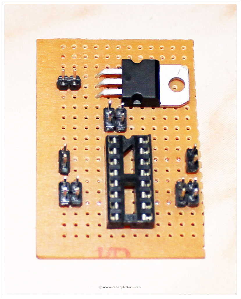
Bend the regulator leads as shown. The middle pin almost touches one of the power pins. If the regulator lead (the middle one) is too long such that it touches both the power pins, cut it short. Vin should also be bent in the same fashion. Vout is bent such that it touches the headers above enable pins.
Tutorial index:
Do you have anything to say?
Visit the Forum to discuss, learn and share anything related to robotics and electronics !!


