How Servo Works?
There are two aspects in understanding a servo. First is “what makes a servo” and second is controlling a servo. In this section, we will concentrate on the first part.
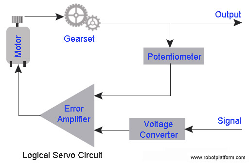
Image shows the block diagram of a typical servo unit. We will understand what each part in the block diagram does and how they together make a servo.
Power Supply: Not shown in the block diagram, but servo needs power supply to run. Most hobby servos are designed to operate at 4.8V to 6V range. If you are looking for a small low voltage servo, or a heavy duty servo, there are specialized servos available which can operate at lower than 4.8V or higher than 6V. Higher the voltage, higher the torque, but make sure not to exceed maximum voltage mentioned in the datasheet.
Signal line: Signal line or control line of a servo is connected to a controller to send coded pulse which determines the angle at which servo shaft should move. This procedure is known as “Pulse Width Modulation”. Servos expect a pulse (active voltage) every 20ms or less (millisecond) and the length of this pulse determines how far the motor should turn. Voltage to signal line can be anything between 3V to 5V to indicate a pulse. Required pulses can either be generated from a timer IC (example: 555) or from a microcontroller.
Voltage converter (a.k.a Voltage decoder): This is a decoder circuit which converts input pulse into corresponding voltage. In other words, when circuit detects a pulse, it charges an internal capacitor at a constant rate while the pulse is high. Once the pulse goes low, capacitor discharges through a buffer amplifier which is fed into error amplifier.
Potentiometer: Pot in a servo acts as a position sensor which detects rotational position of servo shaft. Shaft of the pot is attached to spline (drive shaft) of the servo. When spline rotates, so does the pot shaft changing its resistance. Every rotation angle corresponds to change in resistance in the pot, and resistance at each and every angle produces proportional voltage which is further fed into error amplifier for comparison.
Error Amplifier: Error amplifier in simple words is a voltage comparator (Negative feedback operational amplifier) which receives input voltage from voltage converter and potentiometer. The difference between the two input voltages is amplified and fed into the motor which drives the servo shaft (and the pot shaft). If difference is positive, it drives motor in one direction, else in the other direction until the difference between two voltages is minimized. If the difference is more, circuit drives the motor faster and if less, it drives slower. This same logic can be used in modified servos for controlling speed.
Motor & Gearset: Motor receives angle and polarity input from error amplifier and runs accordingly. Gear set in a servo reduces speed and increases torque.
Note: A servo is never idle and always checks if there is an external signal to correct its position. If you want your servo to hold position, feed continuous appropriate pulses. When servo is held in position and a load tries to move the shaft, it continues to correct its position while drawing more current.
Do you have anything to say?
Visit the Forum to discuss, learn and share anything related to robotics and electronics !!


