Ports & Registers
AVR microcontrollers are register based architectures. All information in the microcontroller like the program memory, state on any of input pins, state of output pins, is stored in registers. There are total 32 x 8 bit registers.
Registers are special storage locations which can store 8 bits of information. This information can be number, an ASCII character code, or even just 8 bits non related to each other.
Atmega8 microcontroller has 23 I/O pins. These pins are grouped under what is known as ports.
So, what are Ports? Ports can be visualized as a gate with specific address between the CPU and external world. CPU uses these ports to read input and write output into them.
Let us take an example of a commonly used µc, the Atmega8. It has 3 ports: PortB, PortC, and PortD. Each of these port is associated with 3 registers - DDRx, PORTx and PINx which sets direction, input and output functionality of ports. Each bit in these registers configures a pin of a port. Bit0 of a register is mapped to Pin0 of a particular port, Bit 1 to Pin1, and Bit2 to Pin2 …etc. They have a one to one relationship between them. Let us discuss each of these registers in detail and their functionality.
DDRx
DDR stands for “Data Direction Register” and ‘x’ indicates port alphabet. As the name suggests, this register is used to set the direction of Port pins to be either input or output. For input, set 0 and for output, set 1. 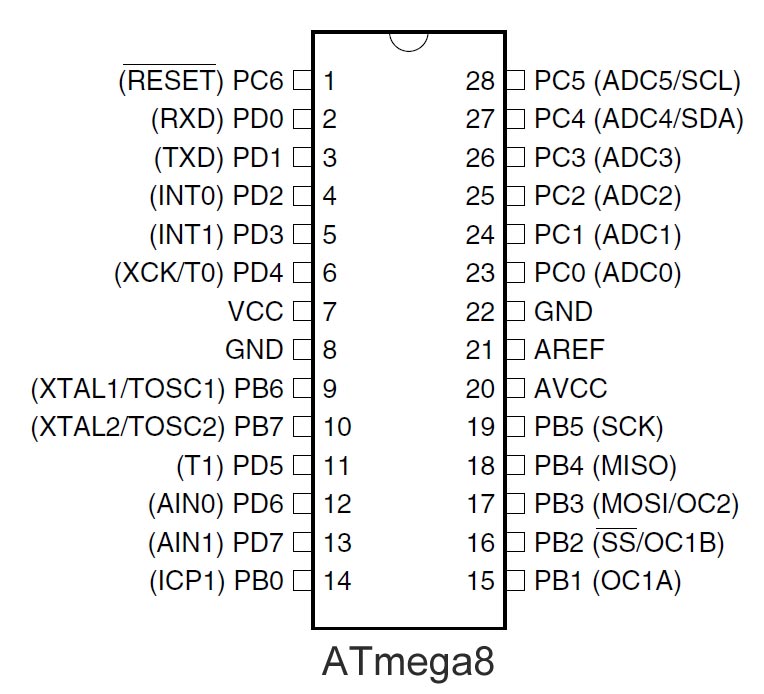
Let us consider PortB, as shown in the figure. To set this port as input or output, we need to initialize DDRB. Each bit in DDRB corresponds to respective pin in PortB.
Suppose we write DDRB = 0xFF, then all bits in PortB are set to Output (1). Similarly, writing DDRB=0x00 configures the port to be Input (0).
What if we need to make few pins of a port as input and others as output? The rules remain the same. Write 1 to the respective pin to make it output and 0 otherwise.
Example, writing DDRB = F0, then the binary equivalent is 11110000. This means the first four pins are set to be Output and the last four pins are set to be Input.
| DDRB: | 1 | 1 | 1 | 1 | 0 | 0 | 0 | 0 |
| PORTB: | PB7 | PB6 | PB5 | PB4 | PB3 | PB2 | PB1 | PB0 |
| Status: | Output | Output | Output | Output | Input | Input | Input | Input |
What happens if there are only 3 pins in a particular port? Nothing happens. Remaining bits are just ignored. As an example, consider a situation where we need to set PortC as input, which has only 7 pins from PC0 through PC6. We still write DDRC = 0xFF and additional 8th bit is simply ignored.
Do you have anything to say?
Visit the Forum to discuss, learn and share anything related to robotics and electronics !!


