AVR Serial Programmer
(Note to readers: I have successfully made this programmer work. However, I have received mails reporting issues with this programmer. Untill I write a complete tutorial, making a better programmer, please consider checking the schematic shown in Ponyprog website, which is much more reliable)
 Programmer act as a liasion between your AVR microcontroller and the PonyProg software. It helps you to upload your .hex file into the AVR microcontroller. There are different types of programmers available in the market. The basic difference between them is the way they connect to the computer or the laptop. Some use Serial interface, while others use the parallel port available. Now the trend is to use USB connector with the USB port available.
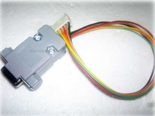
In this tutorial, we will build a simple AVR serial programmer which connects through a RS232 9 pin connector.
If you are not sure how to generate a .hex file, refer "Configure AVR Studio" tutorial, or "Installing PonyProg" to check how to upload your .hex files into your microcontroller.
Parts Required:
| Component | Quantity | Value |
| RS232 - DB9 Female | 1 | - |
| RS232 Case | 1 | - |
| 6 Pin Connector | 1 | - |
| Wire | 6 | 150-200 cms |
| Transistor | 1 | BC547 / BC550/ 2N3904 |
| Resistor | 1 | 15K |
| Resistor | 2 | 10K |
| Resistor | 2 | 4.7K |
| Zener Diode | 3 | 5.1 V Zener Diode |
Once you have received all the above parts, it is just a matter of putting it all together in a desired fashion.
Schematic:
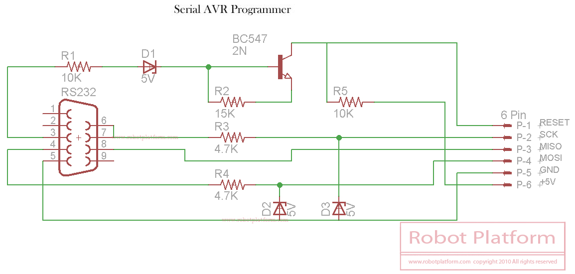
Refer to the above schematic and attach the components together. You can either get a small PCB and solder it all together, or simply plug it on a breadboard and connect it. But it might be difficult for you to use a breadboard with so many connections and pins.
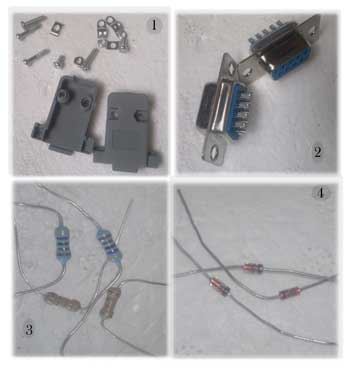
In the image to the right, you can find a few components required to build a serial programmer.
- 1. RS232 case and a set of screws to hold the contents together
- A pair of RS232 - DB9 Female connectors. Of course you need only one of these which can be connected to a PC or a laptop
- Few resistors used in the design.
- 5v Zener diodes
Next time I will try to provide a step-by-step guide to solder all these components together and also how to connect it over a PCB. I have displayed an already created programmer and its design here. If anyone is interested, download the eagle schematic and make modifications if required. Feel free to add your comments in the forum if you face issues while making this serial programmer
Do you have anything to say?
Visit the Forum to discuss, learn and share anything related to robotics and electronics !!


