Resistors in Series:
Resistors are said to be in series when the resistors are chained together in a line. When current is passed, it flows through the entire chain from one resistor to the next, till the last.
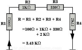
Consider 4 resistors connected in series as shown in the figure with values 100Ω, 1KΩ, 330Ω, 2KΩ. Each of it is connected in series with the next. Since there are connected in series, there is a common current flowing through all. Suppose we send 500mA of current at one end of the circuit, then it remains the same throughout and the same current exists even after passing through the resistor R4.
Hence, Current (I) = 500 mA = I (R1) = I (R2) = I (R3) = I (R4).
If resistors are connected in series, then the total resistance is equal to the sum of resistance from each resistor.
We can rewrite this mathematically as:
R(T) = R1 + R2 + R3 + R4 where R(T) is the total resistance.
= 100 + 1000 + 330 + 2000 (1KΩ = 1000Ω)
= 3430Ω
= 3.43 KΩ or 3.4 KΩ
We have seen that the current throughout the series remains same. However voltage does not remain same throughout as Voltage across resistors is always equal to the potential difference across the connected resistors. This means, Voltage (V) = V (R1) + V (R2) + V (R3) + V (R4). Using Ohm’s law, V = IR, we can calculate Voltage across each resistor. Since voltage across each resistor varies, this circuit can also be used as a “Voltage Divider” when we need different voltages at different points.
Resistors in Parallel:
We have understood resistors in series, what are resistors in parallel? Resistors are said to be connected in parallel if they share a common terminal for each of its end. To visualize it, imagine a vertical railway track with horizontal slabs. If track is the terminal, then the slabs are resistors. When current is passed through, it is divided across each of the resistors as it has different paths to flow.
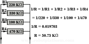
The figure here gives a better picture. Consider 4 resistors connected in parallel as shown with values 220KΩ, 330KΩ, 100KΩ, 470KΩ. To find the total resistance for resistors in parallel, the reciprocal value (1/R) of individual resistors are all added together to get the reciprocal total of resistors.
i.e. 1/R = 1/R1 + 1R2 + 1/R3 + 1/R4, where R is the total resistance.
This is the same for any number of resistors. 1/R = 1/R1 + 1/R2 + 1/R3 + …. 1/Rn, where Rn is the total number of resistors connected in parallel.
However if you have only two resistors in parallel, then the calculation is much straight forward.
R = R1R2 / R1 + R2 where R is the total resistance and R1, R2 are two individual resistors connected.
Other resistor combinations:
There are two other forms of resistor combinations which may not really be used in small circuits. However larger circuits make the best use of them. When you encounter a circuit which is so complex to solve, then there are two main configurations which can assist in solving these circuits. These two resistor combinations are:
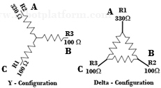
- Y-Configuration or T-Configuration: As the name suggests, resistor formation resembles “Y”, as shown in the figure. The same combination can be rearranged as “T” style and used broadly in large circuits.
- Delta-Configuration: In this style, resistors are arranged in the form or a Delta or a triangle (?).
I will soon write a better tutorial on Y and Delta configuration and conversion between Y to delta and delta to Y.
There are other hybrid categories where a few resistors are coupled in series and the few others in parallel. However, this configuration is required when the requirement is too stringent.
I hope the above tutorial has given you a brief idea about resistors, calculating resistor value and resistor combinations. Feel free to discuss this in the forum in case of any confusion or suggestion, and I will be glad to respond.
Do you have anything to say?
Visit the Forum to discuss, learn and share anything related to robotics and electronics !!


